TM 5-3805-258-24-1
H Y D R A U L I C
S Y S T E M
S Y S T E M S O P E R A T I O N
FLOAT Position
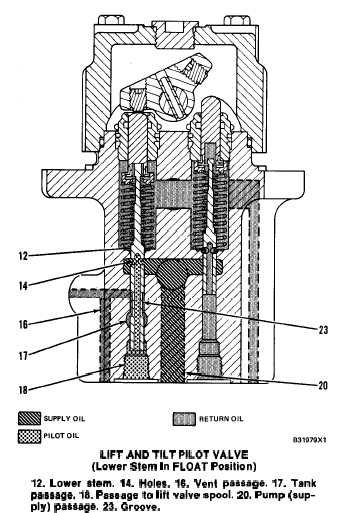
LIFT AND TILT PILOT VALVE
(Lower Stem In FLOAT Position)
12. Lower stem. 14. Holes. 16. Vent passage. 17. Tank
paseage. 18. Paaaage to lift valve epool. 20. Pump (sup-
ply) pasaage. 23. Groove.
When the lift control lever is moved to FLOAT
position, there is a detent that holds the lever in
FLOAT. The movement in the lift and tilt pilot valve
is the same as in LOWER position, except lower stem
(12) is pushed down farther. Vent passage (16) is
now open to tank passage (17) through groove (23).
The oil in vent passage (16) holds the make-up valve,
for the rod end of the lift cylinders, closed in
LOWER position. In FLOAT position, the make-up
valve opens and lets oil from the implement pump
section go directly to drain (tank). There is no pres-
sure oil to the rod end of the lift cylinders, so the
weight of the bucket and lift arms causes the bucket
to lower.
The flow of oil from pump passage (20) through
holes (14) and out passage (18) is the same as in
LOWER position. The lift valve spool is in the same
position in LOWER and FLOAT.
LOWER Position With Engine Off
The bucket can be lowered with the engine off.
The oil supply comes from the head end of the lift
cylinders into pump passage (20). When the lift con-
trol lever is moved to LOWER position and on to
FLOAT position, the bucket will lower to the
ground.
The operation of lower stem (12) is the same as in
FLOAT position when the engine is running. Vent
passage (16) is again opened to tank passage (17)
which vents (releases pressure oil) the make-up
valve for the rod end of the lift cylinders. Oil from
the tank will now go around the lift valve spool to
the rod end of the lift cylinders. The weight of the
bucket and lift arms causes the bucket to lower.
NOTE: When the engine is off and the lift arms are
raised, the bucket can also be dumped.
HOLD Position Of Tilt Operation
When the tilt control lever is in HOLD position,
plungers (26) and (27) are in the same position (as
shown). The plungers do not push up against actua-
tor (24) in the hold position. Pressure oil from the
pilot pump section goes through pump passage (20)
and is stopped by the position of stems (34) and (35).
Holes (36) and (37) are open to tank passage (11).
Spring (33) pushes up on retainer (28) and
plunger (26). Spring (31) holds dump stem (35)
down against retainer (28). Spring (32) pushes upon
retainer (29) and plunger (27). Spring (30) holds tilt
back stem (34) down against retainer (29). There are
spacers between the retainers and plungers that are
used to change the force of springs (30) and (31).
TILT BACK Position
When the tilt control lever is moved to TILT
BACK position, the control lever turns shaft (25)
and actuator (24) in a clockwise direction. The move-
ment of the plunger and stem in the pilot valve is the
same as in RAISE position. Tilt back stem (34)
moves down and oil from pump passage (20) goes
through holes (36). The oil goes out passage (22) to
one end of the tilt valve spool. The tilt valve spool
moves into TILT BACK position.
The oil from the chamber at the opposite end of the
tilt valve spool comes back through passage (21).
This oil goes through holes (37) of dump stem (35)
into tank passage (11).
3-98