H Y D R A U L I C
S Y S T E M
TM 5-3805-258-24-1
S Y S T E M S O P E R A T I O N
DUMP Position
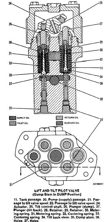
LIFT AND TILT PILOT VALVE
(Dump Stem In DUMP Position)
11. Tank passage. 20. Pump (supply) passage. 21. Pas-
sage to tilt valve spool. 22. Passage to tilt valve spool. 24.
Actuator. 25. Tilt control shaft. 26. Plunger (dump). 27.
Plunger (tilt back). 28. Retainer. 29. Retainer. 30. Meter-
ing spring. 31. Metering spring. 32. Centering spring. 33.
Centering spring. 34. Tilt back stem. 35. Dump stem. 36.
Holes. 37. Holes.
When the tilt control lever is moved to DUMP
position, shaft (25) and actuator (24) turn in a coun-
terclockwise direction (as shown). The movement of
the plunger and stem in the pilot valve is the same as
in LOWER position. Dump stem (35) moves down
and oil from pump passage (20) goes through holes
(37). The oil goes out passage (21) to one end of the
tilt valve spool. The tilt valve spool moves into
DUMP position.
The oil from the chamber at the opposite end of the
tilt valve spool comes back through passage (22).
This oil goes through holes (36) of tilt back stem (34)
into tank passage (11).
DUMP Position With Engine Off
When the lift arms are raised, the bucket can be
dumped with the engine off. The oil supply comes
from the head end of the lift cylinders into pump
passage (20). When the tilt control lever is moved to
DUMP position, the bucket will dump.
The operation of dump stem (35) is the same as in
DUMP position when the engine is running. The
weight of the bucket causes it to dump.
NOTE: See LOWER Position With Engine Off.
ATTACHMENT (THIRD) PILOT VALVE
This pilot valve is for the operation of an addi-
tional or third circuit to control an attachment.
(log fork, side dump or multi-purpose bucket, etc.).
This pilot valve is also controlled manually by the
operator. It gets oil from the lift and tilt pilot valve
and sends it to the attachment valve spool of the
attachment (three spool) control valve. The attach-
ment valve spool sends oil to the attachment cylinder
or cylinders. There are two valve stems (of the pres-
sure metering type) in the attachment pilot valve.
Both stems are used for each operation.
Open or raise stem (14) is the same shape and
operates the same as the raise stem of the lift and tilt
pilot valve. Close or lower stem (15) is longer than
open or raise stem (14), but it operates the same way.
HOLD Position
When the attachment control lever is in HOLD
position, plungers (2) and (3) are in the same posi-
tion. The plungers do not push up against actuator
(1) in the hold position. Pressure oil from the pilot
pump section goes through pump passage (13) and is
stopped by the position of stems (14) and (15). Holes
(11) and (12) are open to tank passage (6).
Spring (9) pushes up on retainer (4) and plunger
(2). Spring (8) holds close or lower stem (15) down
against retainer (4). Spring (10) pushes up on re-
tainer (5) and plunger (3). Spring (7) holds open or
raise stem (14) down against retainer (5). There are
spacers between the retainers and plungers that are
used to change the force of springs (7) and (8).
3-99