HYDRAULIC SYSTEM
TM 5-3805-258-24-1
SYSTEMS OPERATION
is held in passage (19)]. Lift stem (13) is now pushed
off of retainer (6) and is held (floating) in a pressure
modulating position. The lift stem keeps a balance
between the pressure in passage (19) and the force of
spring (7).
When the lift control lever is released, spring (9)
pushes up on plunger (4). Actuator (1) turns shaft
(2) and the lever moves back to HOLD position. Lift
stem (13) moves up because retainer (6) has moved
up (with the plunger) and the force of spring (7) is
less. The oil in passage (19) can now go through holes
(15) and tank passage (11). The centering springs on
the lift valve spool in the lift and tilt control valve
move the valve spool back to HOLD position. The
extra oil from the end of the lift valve spool also goes
through holes (15) and tank passage (11).
NOTE: The farther the lift control lever is moved
into RAISE position, the more plunger (4) and lift
stem (13) move. Thus there is more compression on
spring (7) and the pressure in passage (19) increases.
The lift valve spool now moves farther and lets more
oil go to the head end of the lift cylinders. So the
bucket lifts faster.
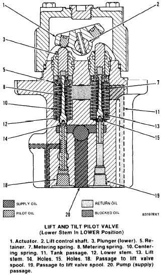
LOWER Position
Lower stem (12) has two purposes: to send pres-
sure oil to the lift valve spool and provide exact
movement of the valve spool during LOWER opera-
tions; to release pressure (vent) in the spring passage
of the make-up valve for the rod end of the lift
cylinders during FLOAT operations.
When the lift control lever is moved into LOWER
position, shaft (2) and actuator (1) turn in the direc-
tion shown. The actuator pushes plunger (3) down
against the force of spring (8). Lower stem (12)
moles down with the plunger. The oil from pump
passage (20) now goes through holes (14) and out
passage (18) to one end of the lift valve spool. The
pressure of this oil, controlled by the force of spring
(8). moves the lift valve spool into LOWER position.
The oil from the chamber at the opposite end of the
lift valve spool comes back through passage ( 19).
This oil goes through holes (15) of lift stem (13) into
tank passage (11).
Oil pressure in passage (18) pushes up against
lower stem (12) and spring (8). A small pressure
increase in passage (18) pushes lower stem (12) up
against the force of spring (8). The flow of pressure
oil through holes ( 14) and passage ( 18) is stopped
[the pressure is held in passage (18)]. Lower stem
(12) is now pushed off of retainer (5) and is held
(floating) in a pressure modulating position. The
lower stem keeps a balance between the pressure in
passage ( 18) and the force of spring (8).
3-97
As the lift control lever [and actuator (1) and
plunger (3)] is moved farther into LOWER position,
plunger (3) comes in contact with lower stem (12).
Holes (14) now become fully open to oil from pump
passage (20). This now moves the lift valve spool
completely to LOWER or full “power down” posi-
tion. The maximum amount of oil now goes to the rod
end of the lift cylinders. So the bucket lowers faster.
When the lift control lever is released, spring (10)
pushes up on plunger (3). Actuator (1) turns shaft
(2) and the lever moves back to HOLD position,
Lower stem (12) moves up because retainer (5) has
moved up (with the plunger) and the force of spring
(8) is less. The oil in passage (18) can now go through
holes (14) and tank passage (11). The centering
springs on the lift valve spool in the lift and tilt
control valve move the valve spool back to HOLD
position. The extra oil from the end of the lift valve
spool also goes through holes (14) and tank passage
(11).