F U E L S Y S T E M
TM 5-3805-258-24-1
T E S T I N G A N D A D J U S T I N G
that follow to determine if the nozzle performance is
acceptable.
I.
II.
III.
IV.
V.
Valve Opening Pressure Test.
Flush the Nozzle.
Tip Leakage Test.
Orifice Restriction Test.
Bleedscrew Leakage Test.
Nozzle Preparation for Test
Before fuel injection nozzle (1) can be tested, all
loose carbon around the tip of the nozzle must be
removed with the 8S2258 Brass Wire Brush (M).
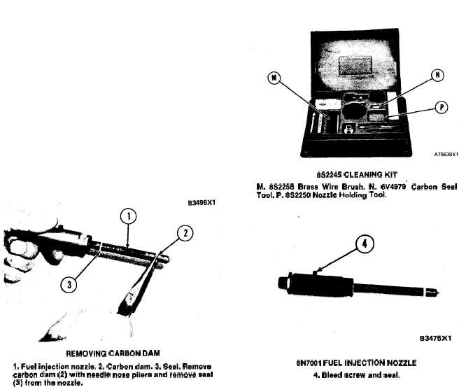
REMOVING CARBON DAM
1. Fuel injection nozzle. 2. Carbon dam. 3. Seal, Remove
carbon dam (2) with needle nose pliers and remove seal
(3) from the nozzle.
CAUTION
Do not use a steel brush or a wire wheel to clean
the nozzle body or the nozzle tip. Use of these
tools can cause a small reduction of orifice
size, and this will cause a large reduction in
engine horsepower. Too much use of the
8S2258 Brass Wire Brush will also remove the
coating that is on the nozzle for protection.
Clean the groove for carbon seal dam (2) and the
body of the nozzle below the groove with the 8S2258
Brass Wire brush (M). Remove the carbon, but be
sure not to use the brush enough to cause damage to
the body of the nozzle.
NOTE: A change in color in the area below the
groove is normal and does not effect the body of the
nozzle.
8S2245 CLEANING KIT
M. 8S2258 Braas Wire Brush. N. 6V4979” Carbon Seal
Tool. P. 8S2250 Nozzle Holding TOOL
8N7001 FUEL INJECTION NOZZLE
4. Bleed screw and seal.
Remove bleed screw and seal (4) from the nozzle.
NOTE: The bleed screw and seal must be removed
for all tests except test V; Bleed Screw Leakage Test.
I. Valve Opening Pressure Test (VOP)
1.
2.
Install 6V2170 Tube Assembly (C) to the tester.
Install 8N7001 Fuel Injection Nozzle with
5P7448 Adapter (A) on tube assembly (6). Posi-
tion the bleed screw hole toward the tester and in
line with 6V2170 Tube Assembly (C). This will
make the fuel spray pattern horizontal. Be sure
the nozzle tip is down and extends into FT1384
Extension (F) and 8S2270 Fuel Collector (J).
4-7