F U E L S Y S T E M
TM 5-3805-258-24-1
T E S T I N G A N D A D J U S T I N G
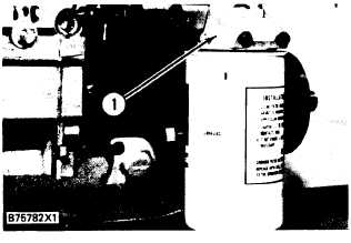
1. Remove fuel filter base (1) and the fuel line
from the fuel filter base to the fuel transfer
pump.
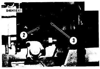
2. Remove bolts (2) and timing pin cover (3) from
the fuel injection pump housing.
4.
5.
6.
7.
With the timing pin in position, move the gov-
ernor lever to the high idle position. The fuel
rack will move until the edge of the groove in
the rack makes contact with the timing pin.
The fuel rack is now in the center position.
Fasten the governor lever in the HIGH IDLE
position.
Remove the fuel injection line from the fuel
injection pump.
Put the 8S4613 Wrench into spline of bushing
that holds the fuel injection pump in the hous-
ing. Remove the bushing.
Install 8S2244 Extractor (5) on the threads of
F U E L I N J E C T I O N P U M P H O U S I N G
1. Fuel filter base.
CAUTION
The fuel rack MUST BE IN THE CENTER POSl-
TION before the correct installation of an injec-
tion pump is possible.
F U E L I N J E C T I O N P U M P H O U S I N G
2. Bolts. 3. Timing pin cover.
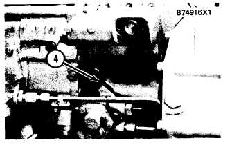
3. Move the governor lever to the FUEL OFF
position and install timing pin (4) in the rack
centering hole as shown.
the injection pump. Carefully pull the pump
straight up out of the bore.
Be careful when an injection pump is disassem-
bled. Do not damage the surface on the plunger. The
plunger and barrel are made as a set. Do not put the
plunger of one pump in the barrel of another pump. If
one part is worn, install a complete new pump assem-
bly. Be careful when the plunger is put into the bore
of the barrel. When injection pumps and spacers are
removed from the fuel injection pump housing, keep
the parts together so they can be installed in the same
location in the housing.
Installation of Fuel Injection Pumps
1.
2.
3.
4.
5.
Put the fuel rack in the center position. Make
reference to Removal of Fuel Injection Pumps.
Put 8S2244 Extractor (5) on the threads of the
fuel injection pump.
Make sure the lifter for the pump to be installed
is at the bottom of its travel.
Put the groove of barrel (6) in alignment with
the middle (fourth) tooth of gear segment (7).
Look into the bore for the fuel injection pump
and locate both dowels. There is a dowel in the
lifter and a dowel in the opposite side of the bore
in the fuel injection pump housing. Put the
groove in the pump barrel in alignment with the
large dowel in the pump housing and put the slot
(groove) on the opposite side of the gear teeth on
the sector gear in alignment with the small dowel
T I M I N G P I N I N S T A L L E D
4. Timing pin.
4-11


