A I R I N L E T A N D E X H A U S T S Y S T E M
TM 5-3805-258-24-1
T E S T I N G
A N D
A D J U S T I N G
CRANKCASE (CRANKSHAFT
COMPARTMENT) PRESSURE
Pistons or piston rings that have damage can be the
cause of too much pressure in the crankcase. This
condition will cause the engine to run rough. There
will also be more than the normal amount of fumes
coming from the crankcase breather. This crank-
shaft pressure can also cause the element for the
crankcase breather to have a restriction in a very
short time. It can also be the cause of oil leakage at
gaskets and seals that would not normally have
leakage.
Normal crankcase pressure with a clean crankcase
breather is 50.8 mm (2 in.) of water or less.
CYLINDER HEAD
The cylinder head has valve seat inserts and valve
guides that can be removed when they are worn or
have damage. Replacement of these components can
be made with the tools that follow.
Valves
Valve removal and installation is easier with use of
5S1330 Valve Spring Compressor Assembly and
5S1322 Valve Keeper Inserter.
Valve Seat Inserts
Tools needed to remove and install valve seat inserts
are in the 6V4805 Valve Insert Puller Group. Spe-
cial Instruction Form No. SMHS7935 gives an ex-
planation for this procedure. The insert can be more
easily installed by lowering the temperature of the in-
Valve Guide
Tools needed to install valve guides are: 7S8858
Driver Bushing and 7S8859 Driver. The counterbore
in the driver bushing installs the guide to the correct
height. Use a 1P7450 Honing Arrangement to make
a finished bore in the valve guide after installing the
guide in the head. Special Instruction Form No.
SMHS7526 gives an explanation of this procedure.
Grind the valves after installing new valve guides.
VALVE CLEARANCE
NOTE: Valve clearance is measured between the
rocker arm and the valves.
VALVE CLEARANCE CHECK: ENGINE STOPPED
Exhaust . . . . . . . . . . . . . . . . . . 0.56 to 0.71 mm (.022 to .026 in.)
Intake . . . . . . . . . . . . . . . . . . . . 0.30 to 0.46 mm (.012 to .018 in.)
NOTE: When the valve lash (clearance) is checked,
adjustment is NOT NECESSARY if the measure-
ment is in the range given in the chart for VALVE
CLEARANCE CHECK: ENGINE STOPPED. If
the measurement is outside this range, adjustment is
necessary. See the chart for VALVE CLEARANCE
SETTING: ENGINE STOPPED, and make the set-
ting to the nominal (desired) specifications in this
chart.
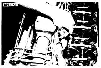
V A L V E C L E A R A N C E C H E CK
( T Y P I C A L
E X A M P L E)
V A L V E C L E A R A N C E S E T T I N G : E N G I N E S T O P P E D
Exhaust . . . . . . . . . . . . . . . . . . . . . . . . . . . . . . . . . . . . . . . . . ...0.64 mm (.025 in.)
Intake . . . . . . . . . . . . . . . . . . . . . . . . . . . . . . . . . . . . . . . . . . . . . .. 0.38 mm (.015 in.)
1. Put No. 1 piston at top center (TC) on the
compression stroke. Make reference to FIND-
ING TOP CENTER COMPRESSION POSI-
sert before installing it in the head.
4-27
TION FOR NO. 1 PISTON.


