F U E L S Y S T E M
TM 5-3805-258-24-1
T E S T I N G
A N D
A D J U S T I N G
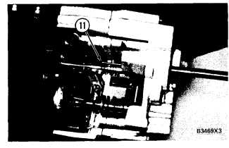
NOTE: The 6V2128 Compressor is used to com-
press the over fueling spring. The over fueling
spring must be compressed to get an accurate fuel
rack measurement. When the compressor is in-
stalled, the end of the compressor contacts and
moves collar (11) in the governor.
14.
I N S I D E V I E W O F G O V E R N O R
11. Collar.
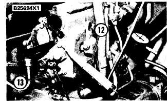
10. Fasten the clip end of 8S4627 Circuit Tester
(12) to the rack contact on the rear of the gov-
ernor housing and put the other end to a good
electrical ground.
C I R C U I T
T E S T E R
I N S T A L L ED
( T Y P I C A L E X A M P L E)
12. 8S4627 Circuit Tester. 13. Cover.
11. Hold the governor lever in the FUEL ON
position. Turn the bolt in compressor (10) in
(clockwise) as far as it will go. This removes
the free play inside the governor.
12. Now turn the bolt out (counterclockwise)
until the light just comes on (dim light). This
is the static fuel setting. Make reference to
the FUEL SETTING INFORMATION for
the correct static fuel setting, and compare
with the reading on the dial indicator.
13. If the static fuel setting is not correct, remove
lockwire and seal, and cover (13) from the rear
of the governor.
P O W E R A D J U S T M E N T S C R EW
( T Y P I C A L
E X A M P L E )
14. Power adjustment screw.
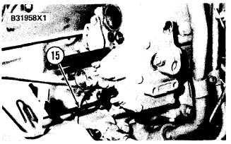
Install 6V2106 Rack Adjustment
Tool Group
(15) on power adjustment screw (14) and lock-
nut.
A D J U S T I N G
S T A T I C
F U E L
S E T T I N G
( T Y P I C A L E X A M P L E)
15. 6V2106 Rack Adjustment Tool Group.
15. Loosen the locknut and turn the power adjust-
ment screw to change the static fuel setting.
Turn the power adjustment screw clockwise to
decrease the static fuel setting. Tighten the
locknut.
NOTE: One half of a turn of the power adjustment
screw will change the static fuel setting approxi-
mately 0.40 mm.
16. Again check the static fuel setting. If the static
fuel setting is correct, remove all tools and
install plug (9), covers (3 and 13) and the air
fuel ratio control. Install new wire and seal.
MEASURING ENGINE SPEED
T o o l s
N e e d e d :
6 V 3 1 2 1 M u l t i t a c h G r o u p
The 6V3121 Multitach Group can measure engine
speed by the use of either the photo pickup and
reflective tape, or a magnetic pickup or tachometer
generator. Special Instruction Form No. SEHS7807
has instructions for its use.
4-23


