TM 5-3805-258-24-1
A I R S Y S T E M A N D B R A K E S
T E S T I N G A N D A D J U S T I NG
EMERGENCY AND PARKING
BRAKE ADJUSTMENT
E M E R G E N C Y A N D P A R K I N G B R A KE
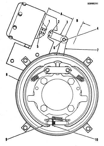
1. Rod. 2. Nut. 3. Rod end. 4. Cotter. 5. Nut. 6. Pin. 7.
L e v e r . 8 . D r u m . 9 . S h o e ( t w o ) . 1 0 . S t a r w h e e l . A . D i -
mension from face of mounting bracket to center of pin (6).
B. Stroke of lever (7).
WARNING
Make reference to WARNING on first page of
AIR SYSTEM AND BRAKES TESTING AND AD-
JUSTING section,.
1.
2.
3.
4.
5.
6.
7.
8.
9.
Start the engine and let the air pressure go up to
operating range.
Move the control knob for the parking brake to
OFF (brake released) position. Stop the engine.
Remove cotter (4) and pin (6). Remove lever (7)
from its shaft.
Turn starwheel (10) to get a clearance between
shoes (9) and drum (8) of..
(.010 ± .005 in.)
Loosen nut (2) and turn rod
mension (A) of . . . . . . . . . . . . . . . . . . . .
install lever (7), pin (6) and
0.25 ± 0.12 mm
end (3) to get di-
100.0 mm (3.94 in.)
cotter (4).
Usc nut (5) to turn rod (1) until free movement
between rod end (3) and lever (7) is removed.
Tighten nut (2).
Move the control knob for the parking brake to
ON (brake engaged) position and check the
stroke [distance (B)]. Do Steps 1 through 8
again if distance (B) is more than 19.0 mm (.75
in.)
NOTE: The parking brake is adjusted correctly if the
machine can not be moved in first speed forward.
4-66