H Y D R A U L I C
S Y S T E M
TM 5-3805-258-24-1
T E S T I N G
A N D
A D J U S T I N G
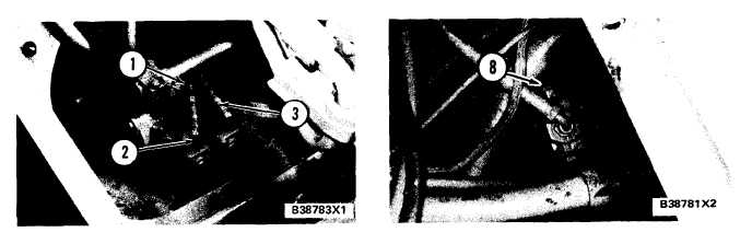
F R O N T O F L O A D E R F R A ME
1. Hose assembly from tilt back stem of pilot valve. 2.
Elbow. 3. Hose assembly from lift stem of pilot valve.
4.
5.
6.
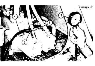
T Y P I C A L T I L T B A C K P R E S S U R E T E ST
4. 6V3081 Hose. 5. 5P5008 Connector. 6. 619258 Swivel
T e e . 7 . 5 P 4 8 1 5 P r e s s u r e G a u g e .
Install hose (4) with pressure gauge (7) (0 to 4150
kPa or 0 to 600 psi) on the connector.
Start and run the engine at high idle rpm. Move
and hold the tilt control lever to TILT BACK
position.
When the bucket is completely tilted back, read
the pressure on the gauge. The pressure, with the
oil at normal operating temperature, will be ap-
proximately 140 kPa (20 psi) less than the pres-
sure at the pump.
7. If the pressure on the gauge is not correct, re-
move plug (8) from the relief valve. Remove the
spring and the cartridge valve. Install a new
cartridge valve, the spring and plug (8).
P I L O T P U M P S E C T I O N R E L I E F V A L VE
8. Plug.
Pilot Pressure For Dump
8. To check the pressure from the dump stem, re-
move the swivel tee from hose assembly (1)
and install it between hose assembly (9) and its
elbow.
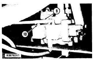
B A C K O F L I F T A N D T I L T C O N T R O L V A L V E
9. Hose assembly from dump stem of pilot valve. 10. Con-
nector in line from lower stem of pilot valve.
9. Move the bucket completely to the dumped posi-
tion. Do Steps 5 and 6 again, only this time move
the tilt control lever to DUMP position. The
pressure on the gauge must be the same as in
step 6.
Pilot Pressure For Lift
10. To check the pressure from the lift stem, re-
move the swivel tee from hose assembly (9)
and install it between hose assembly (3) and
its elbow.
4-71