H Y D R A U L I C
S Y S T E M
TM 5-3805-258-24-1
T E S T I N G
A N D
A D J U S T I N G
HYDRAULIC SYSTEM
WARNING
Hydraulic oil, under pressure that can be
higher than 34500 kPa (5000 psi) can remain in
the hydraulic system on this machine after the
engine and pump have been stopped. Sudden
movement of the machine or release of oil
under pressure can cause injury to persons on
or near the machine. To prevent possible in-
jury, do the procedure that follows before test-
ing and adjusting the hydraulic system:
1.
2.
3.
4.
5.
6.
7.
8.
9.
Move the machine to a smooth horizontal loca-
tion. Move away from working machines and
personnel.
Permit only one operator on the machine. Keep
all other personnel either away from the
machine or in view of the operator.
Activate the parking brake. With the engine run-
ning, put the bucket flat on the ground. When
the bucket is raised for tests or adjustments, be
sure that the bucket has correct support and the
bucket is in the full dump position. The lift cir-
cuit has high oil pressure when the lift arms
raise the front of the machine. DO NOT STOP
THE ENGINE with the front of the machine off
of the ground.
Install the anti-pivot link.
Make sure all hydraulic pressure is released
before any fitting, hose or component is
loosened, tightened, removed or adjusted.
Move the lift control lever to FLOAT position.
Shut off the engine.
Move the lift control lever to the HOLD position.
Carefully loosen the filler cap on the hydraulic
tank to release the pressure.
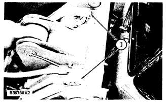
10. Carefully loosen plugs (1) at the rear of the tilt
cylinder. When the oil from the loosened plugs
stops, tighten the two plugs.
NOTE: To release the pressure in the attachment
cylinders, carefully loosen two large plugs near
11. Tighten the filler cap on the hydraulic tank.
12. The pressure in the system has now been
released and lines or components can be
removed.
R E A R O F T I L T C Y L I N D ER
1. Plugs.
During a diagnosis of the hydraulic system, re-
member that correct oil flow and pressure are neces-
sary for correct operation. The output of the pump
(oil flow) increases with an increase in engine speed
(rpm) and decreases when engine speed (rpm) is
decreased. Oil pressure is caused by resistance to the
flow of oil.
Visual checks and measurements are the first step
when troubleshooting a possible problem. Then do
the Operation Checks and last the Instrument Tests.
Use the 5S5123 Hydraulic Test Group, 6V4161
Hydraulic Test Group, a stop watch, a magnet, a
thermometer and a mm (inch) ruler for basic tests
to measure:
1.
2.
The pressure of the oil to open the relief valves
for the main and pilot systems and the relief
valves for the tilt circuits. Relief valve pressures
that are too low will cause a decrease in the lift
and the dig characteristics of the machine. Pres-
sures that are too high will cause a decrease in
the life of hoses and components.
Drift rates in the lift and tilt circuits: Circuit
drift is caused by a leakage past cylinder pistons,
O-ring seals in the control valves, check valves or
make-up valves that do not seat correctly or poor
adjustment or fit in the control valves.
plugs (1) at the top of the loader frame. When the oil
from the loosened plugs stops, tighten the two large
plugs.
4-67