A I R S Y S T E M A N D B R A K E S
TM 5-3805-258-24-1
T E S T I N G
A N D
A D J U S T I N G
has now been removed from the system so
that the other wheel brake on the axle can
be checked for leakage.
d. Do Steps 2 through 5 again. If brake fluid
loss from the reservoir is the same as before,
there is no leakage in the brake that has
been removed from the system (blocked).
e. Do Steps 6b through 6d again for the other
brake on the same axle. This gives added
proof to the location of the problem.
Correction
After the location of the leakage is found, use the
procedure that follows to correct brake problems.
1. For hose, tube or fitting leaks; tighten, repair or
replace connections as needed.
2. If the leakage is in a master cylinder, replace
seals (1), (2) and (3) of the master cylinder. It is
also possible that some other defect, that can be
easily seen, will need correction. Also, rippling
(roughness) may be found in the bore of the
master cylinder. This condition is not desired.
Correct any damage or problem that can be
easily found.
3. If the leakage is in a wheel brake head assem-
bly, replace seals (4) and (5) of the head assem-
bly, or replace the complete head assembly.
REMOVE AIR FROM THE WHEEL BRAKE
HYDRAULIC CIRCUIT
(BLEED THE BRAKES)
WARNING
Make reference to WARNING on first page of
AIR SYSTEM AND BRAKES TESTING AND AD-
JUSTING section.
Air must not be in the hydraulic circuit. Air in the
system can prevent complete brake application and it
is possible that the wheels on the machine can not be
stopped.
NOTE: Keep both brake fluid reservoirs full of brake
fluid during the air removal procedure.
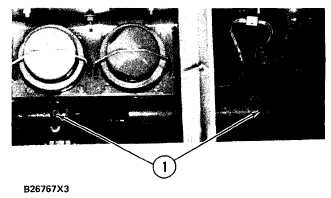
B L E E D E R S C R E W S F O R T H E M A S T E R C Y L I N D E R S
1. Bleeder screws for the master cylinders.
1. Start the engine and let the air pressure go up to
normal pressure for operation. Keep the engine
in operation during this procedure to make sure
of correct air pressure.
2. Push and hold the right brake pedal down.
3. Loosen (open) bleeder screws (1) on the master
cylinders.
4. Tighten (close) bleeder screws (1) and release
the right brake pedal.
5. Do Steps 2 thru 4 again until there is a constant
flow of brake fluid (all of the air is removed)
from each bleeder screw on the master cylinders.
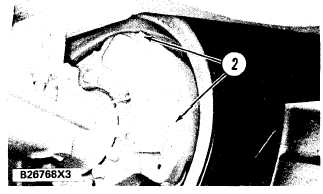
B L E E D E R S C R E W S F O R T H E W H E E L B R A K E
2. Bleeder screws.
6. Push and hold the right brake pedal down.
NOTE: Bleed only one wheel at a time.
7. Open bleeder screws (2) at a wheel brake.
8. Close bleeder screws (2) and release the right
brake pedal.
9. Do Steps 6 thru 8 again until there is a constant
flow of brake fluid from bleeder screw (2).
10. Do Steps 6 thru 9 again at each wheel brake until
all of the air is removed from the system.
4-63