TM 5-3805-258-24-1
H Y D R A U L I C
S Y S T E M
11. Lift the lift arms as high as they will go. Do
Steps 5 and 6 again only this time move the lift
control lever to RAISE position. The pressure
on the gauge must be the same as in Step 6.
Pilot Pressure For Lower And Float
12.
13.
14.
15.
To check pressure for the lower stem, remove
the swivel tee from hose assembly (3) and in-
stall it between the hose assembly and elbow
at connector (10).
Lower the bucket to the ground. Do Steps 5 and
6 again, only this time move the lift control lever
to FLOAT position. The pressure on the gauge
must be the same as in Step 6.
Release the pressure in the hydraulic system and
remove the test equipment.
Remove the air in the pilot system. See PROCE-
DURE TO REMOVE AIR FROM PILOT
SYSTEM.
PROCEDURE TO REMOVE AIR FROM PILOT
SYSTEM
WARNING
Make reference to WARNING on first page of
LOADER HYDRAULIC SYSTEM TESTING AND
ADJUSTING section. Air in the pilot system can
cause an extremely dangerous condition. The
bucket can drop whenever the engine stops or
is shut off. If this condition happens the proce-
dure that follows should correct the problem.
TOOIS Needed:
6V4161 Hydraulic Test Group
5H4018 Cover
5H4019 Covers (Two)
F R O N T O F L O A D E R F R A M E
1. Hose assembly to rod end of tilt cylinder. 2. Bleed screw
for tilt back operation. 3. Bleed screw for raise operation.
4-72
T E S T I N G
A N D
A D J U S T I N G
NOTE: Loose oil line connections and hoses or lines
that have oil leakage will let air into the hydraulic
system.
1.
2.
3.
4.
Disconnect hose assembly (1) from the tilt
cylinder.
Install a 5H4019 Cover between the hose assem-
bly and the tilt cylinder. Connect hose assembly
(1) to the tilt cylinder.
Install a 5H4018 Cover between hose assem-
blies (6) and (7) and their blocks.
Start and run the engine at low idle.
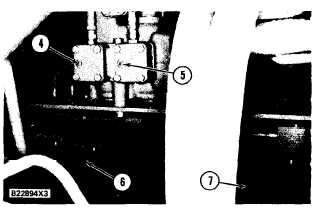
B A C K O F L I F T A N D T I L T C O N T R O L V A L VE
( T Y P I C A L )
4. Bleed screw for lower and float operations. 5. Bleed
screw for dump operation. 6. Hose assembly to rod end
of left lift cylinder. 7. Hose assembly to rod end of right
lift cylinder.
5.
6.
7.
8.
9.
10.
11.
12.
13.
Move the tilt control lever to TILT BACK
position.
Loosen (open) bleed screw (2). Keep it open
until there is a constant flow of oil (no air bub-
bles) from bleed screw (2).
Tighten (close) bleed screw (2). Release the tilt
control lever.
Move the tilt control lever to DUMP position.
Open bleed screw (5). Keep it open until there is
a constant flow of oil (no air bubbles) from the
bleed screw.
Close bleed screw (5). Release the tilt control
lever.
Move the lift control lever to RAISE position.
Open bleed screw (3). Keep it open until there is
a constant flow of oil from the bleed screw.
Close bleed screw (3). Move the lift control lever
to HOLD.