S I N G L E C Y L I N D E R
A I R C O M P R E S S O R
TM 5-3805-258-24-1
T E S T I N G A N D A D J U S T I N G
TESTING AND ADJUSTING
The air pressure gauge will show low air pressure
in the system when air system checks or tests are
needed. Air system checks are needed if the needle
in the air pressure gauge keeps moving when the
components in the air system are not being used.
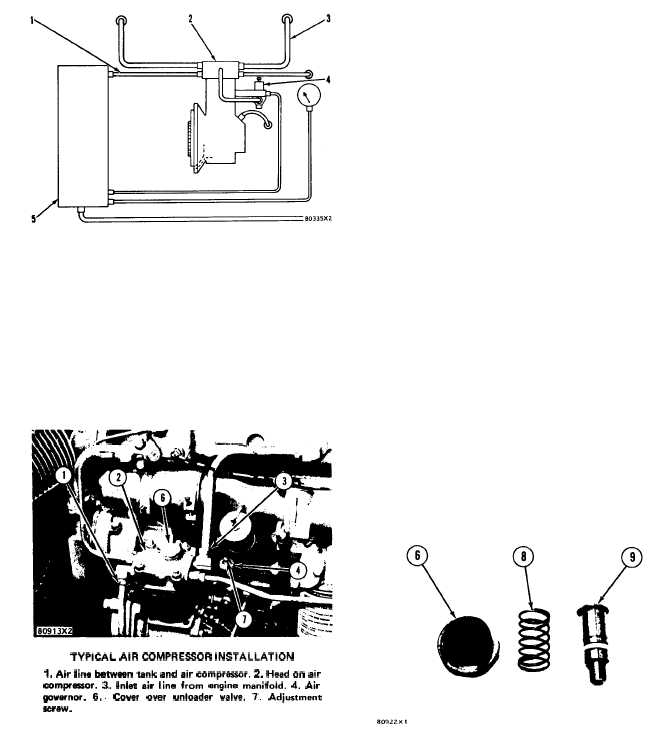
AIR SYSTEM SCHEMATIC
1. Air line between tank and air compressor. 2. Head for air
compressor. 3. Inlet air line from engine manifold. 4. Air
governor. 5. Air tank.
The complete air system, including the com-
ponents in the air system, must be checked for any
air leaks. The air lines must have no breaks and all
of the air line connections must be tight and have
no air leaks. If all of the air leaks have been
stopped and the air pressure gauge still has indi-
cations of low air pressure further tests are needed.
TYPICAL AIR COMPRESSOR INSTALLATION
1. Air line between tank and air compressor. 2. Head on air
com~eaaor. 3. Inlet air line from angine manifold. 4. Air
@vernor. 6.. Cover over unloader valve. 7. Adjustment
Screw.
Stop the engine and let all of the air out of the
tank (5) and the air system. Disconnect line (1)
from the cylinder head (2) to the air tank.
4 - 81
Start the engine and let it run for a minute. With
the engine running hold a white card approxi-
mately 2 in. (50.8 mm) from the opening in the
head (2), where air line (1) was disconnected but
for no more than 10 seconds. A large area of oil on
the card is an indication of wear either in the bore
of the liner or the piston rings (and piston). A little
oil in fine drops is an indication of correct lubri-
cation. If the card test shows no wear, connect air
line (1) and let the air compressor fill the air tank
until the air pressure gauge will not indicate any
more pressure.
Run the engine at low idle speed and disconnect
air inlet line (3) from the cylinder head (2). With
the engine still running slow, hold, your hand close
to the opening in head (2) where air line (3) was
disconnected. If air can be felt coming from the
opening when the piston of the air compressor is
on the compression stroke, the inlet valve is not
closing. Either the unloader valve under cover (6) is
holding the inlet valve open or there is dirt on the
inlet valve holding it open. A broken spring under
the inlet valve will also keep the valve open.
The unloader valve can be cleaned by removing
cover (6), spring (8) and unloader valve (9). Clean
the unloader valve and the passage in the head
where the unloader valve fits.
Install the unloader valve, the spring and the
cover. Torque for cover (6) is 60 lb. ft. (8.3 mkg).
Start the engine and feel for air coming from the
opening where air line (3) was disconnected, if air
can be felt the inlet valve is not closing and the
head assembly must be removed to clean the inlet
valve.
UNLOADER VALVE
6. Cover. 8. Spring. 9. Unloader valve.


