H Y D R A U L I C
S Y S T E M
CONTROL LEVER LINKAGE ADJUSTMENT
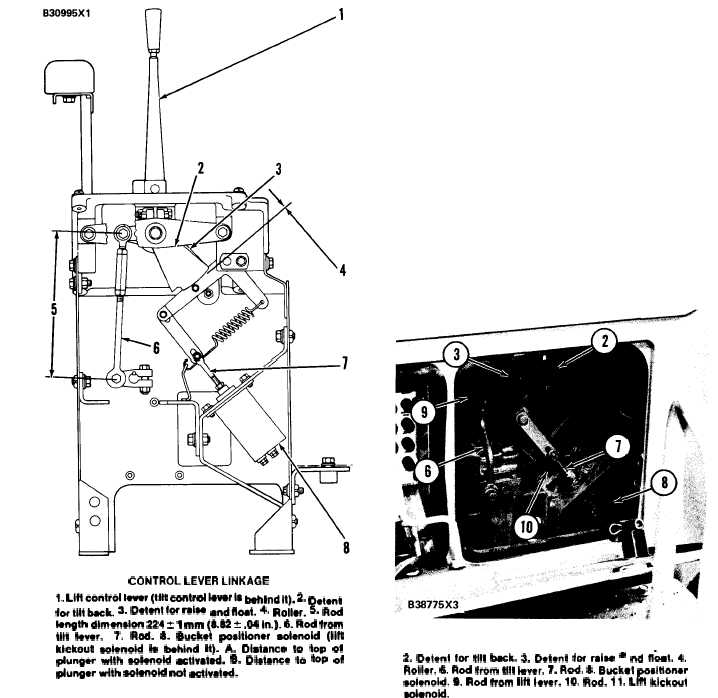
CONTROL LEVER LINKAGE
l. Llftcontrol lever (tilt COntikwrls Mlndlt). 2. D@ent
lortlltbeck. 3. Dotentbrrcieew Idffat. 4. Roller. S. Rod
length dimension 224 t 1 mm (8.32? .04 in.). 6. Rod from
tilt fever.
7. Rod. 8. Bucket positioner eolenoid (lift
kickout eolonoid b behind it). A. Distcnce to top ot
plunger with eolenotd ectivated. B. Diet-e to toP of
pfunger wfth colenokf not ectivated.
TM 5-3805-258-24-1
T E S T I N G
A N D
A D J U S T I N G
Control lever linkage adjustment must be made
with the lift arms at maximum height and the buck-
et in the tilt back position. This is done so that both
the lift and tilt (bucket positioner) kickout solenoids
can be easily activated.
1.
2.
3.
Make sure that the lift kickout and bucket
positioner are adjusted correctly. The magnet for
the lift kickout must be in the correct position.
The switch for the bucket positioner must be in
the correct position. See their respective AD-
JUSTMENT PROCEDURES.
Open the cover on the right side of the cab.
Rods (6) and (9) must have length dimension (5)
of 224 ± 1 mm (8.82 ± .04 in.) between the
centers of the bolts through the ends. Loosen
a locknut against an end and remove the bolt
through the end of the rod. Turn the end either
clockwise or counterclockwise to change the
length of the rod.
R I G H T S I D E O F C AB
2. Detent for tilt beck. 3. Detent for rcise l nd ft-mt. 4.
Roller. 6. Rod from tilt lever. 7. Rod. 8. Bucket positioner
soienoid. 9. Rod from lift iever. 10. Rod. 11. Lfff kickout
eoienoid.
4-79