ENGINE
TM 5-3805-258-24-2
DISASSEMBLY AND ASSEMBLY
TIMING GEARS AND PLATE
CAUTION
After the timing gear plate is installed be sure
the rack is free to move in the fuel injection
pump housing. The O-ring seal on the drive end
of the fuel injection pump housing can hold the
rack and prevent free rack movement. Rack
movement can be seen through hole (3) in the
timing gear plate. If the rack does not move
freely, remove the timing gear plate and check
the O-ring seal on the drive end of the fuel
injection pump housing.
4.
5.
6.
7.
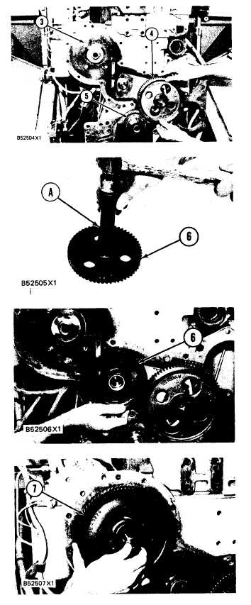
Install camshaft gear (4) on the camshaft so
the “C” marks on both crankshaft gear (5) and
camshaft gear (4) are in alignment. Install the
bolts that hold camshaft gear (4) on the cam-
shaft and tighten them to a torque of 55 ± 7
N·m (41 ± 5 lb. ft.).
Use tool (A) and install the bearing
gear (6). The end of the bearing must
in idler
be 1.52
mm (.060 in. ) below the face of the gear hub.
Be sure the oil hole in the shaft for gear (6) is
open. Install idler gear (6) on the shaft. Put the
plate in position with the finished side toward
gear (6) and install the bolts that hold the plate
and gear (6) on the shaft.
Put fuel injection pump drive gear (7) in posi-
tion on the fuel injection pump camshaft. In-
stall the washer and bolt that hold the gear in
place but do not tighten. The flat side of the
washer must be away from the gear. For cor-
rect installation of the fuel injection pump drive
gear and timing of the engine, see INSTALL
FUEL INJECTION PUMP HOUSING AND
GOVERNOR.
end by:
a) install timing gear cover
5-75