TM 5-3805-258-24-2
ENGINE
DISASSEMBLY AND ASSEMBLY
16.
17.
18.
19.
20.
GOVERNOR
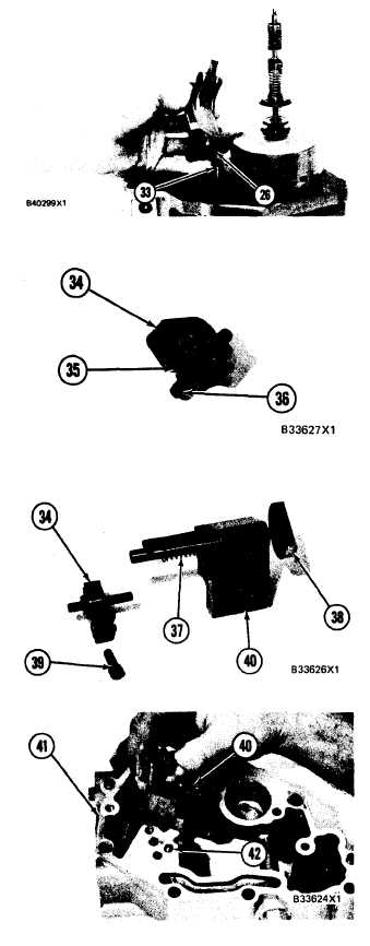
Put the governor servo in position on the fuel
injection pump housing with piston (26) en-
gaged over rack (33) and install the bolts that
hold the governor servo in place.
Install torque rise adjustment screw (36) in
collar (34) as shown and install locknut (35) on
the screw.
Install bolt (38) in block (40) as shown. Install
spring (37) on bolt (38) as shown. Put collar
(34) in position on bolt (38) with the hole in the
collar in alignment with the notch in bolt (38)
and install bolt (39) to hold the collar in place.
Put block (40) in position on housing (41) with
the holes in the block in alignment with dowels
(42). Install the bolts that hold the block in
place.
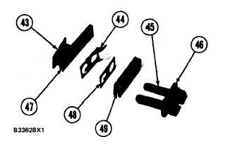
Assemble the torque control group as follows:
a) Install bar (47), contact (44), spacer (48)
on insulator (43) as shown.
b) Install retainer (46), bar (49) and the insu-
lator assembly on bolts (45) as shown.
5-115


