TM 5-3805-258-24-2
ENGINE
DISASSEMBLY AND ASSEMBLY
VALVE COVER
REMOVE VALVE COVER
1107-11
1.
2.
3.
4.
5.
6.
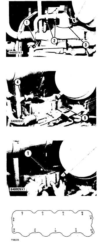
Put marks on wire assembly (1) for correct
connection.
Disconnect wires (1) from the sending unit.
Remove the bolts and move wire assembly (1)
away from the valve cover.
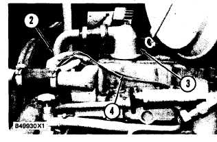
Loosen clamps (2) and slide the hose on the
breather tube. Remove breather (3) from the
valve cover.
Turn breather tube (4) away from valve cover
(5).
Remove the bolts, valve cover (5) and the gas-
ket from the engine.
INSTALL VALVE COVER
1107-12
1.
2.
3.
4.
5.
6.
Install a new gasket for the valve cover if need-
ed. Use 5H2471 Cement to hold the new gasket
to the valve cover.
Put valve cover (1) in position on the cylinder
head. Install the bolts that hold the valve cover
in place. Tighten the bolts in number sequence
shown to a torque of 11 ± 3 N·m (8 ± 2 lb. ft.).
Put breather (3) in position on the valve cover.
Tighten the bolts to a torque of 14 ± 3 N·m (10
± 2 lb.ft.).
Put breather tube (2) in position and slide the
hose into the breather. Tighten the hose
clamps.
Put wire assembly (4) in position and connect
the clips to the engine.
Connect the wire assembly to the sending unit.
.
5-120