ENGINE
TM 5-3805-258-24-2
DISASSEMBLY AND ASSEMBLY
GOVERNOR
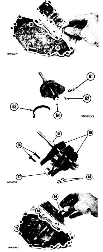
29. Put lever (59) in position in the housing as
shown and install shaft (60) to hold the lever in
place.
30. Install spring (63) in shaft assembly (64). In-
stall pin (61) in the shaft assembly (64) with
the tip of the pin engaged in the hole in spring
(63). Install pin (62) in the shaft assembly to
hold pin (61) in place.
31. Put stop (67) and plates (65) in position on
shaft assembly (64) and install pins (66) to hold
the plates and stop in place. Install snap rings
(68) to hold pins (66) in place.
32. Put levers (69) and (70) in position in the hous-
ing as shown and install shaft assembly (64) to
hold the levers in place.
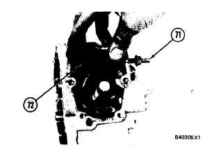
33. Install adjustment screw (71) and the locknut
for the low idle adjustment in the housing. In-
stall spring (72) in the hole in the shaft assem-
bly and in the housing.
5-117