TM 5-3805-258-24-2
ENGINE
GOVERNOR
DISASSEMBLY AND ASSEMBLY
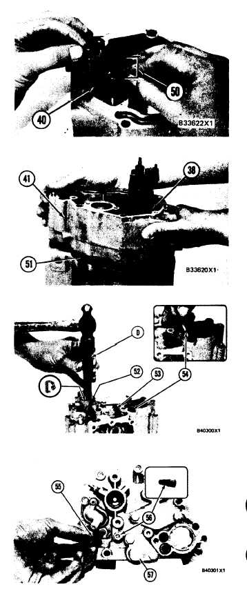
21. Install torque control group (50) on block (40)
as shown.
WARNING
If housing (41) is installed with the flange on
bolt (38) on the wrong side of the dashpot, the
riser in the governor will be held in the maxi-
mum fuel delivery position. To prevent possi-
ble personal injury make sure housing (41) is
installed on the fuel injection pump housing
with the flange on bolt (38) behind the dashpot.
22.
23.
24.
25.
26.
27.
28.
29.
Install gasket (51) on the fuel injection pump
housing. Put housing (41) in position on the
fuel injection pump housing with bolt (38) be-
hind the dashpot as shown. Install the bolts that
hold housing (41) in place.
Use tooling (D) to install lip type seal (52) in
the governor outer housing with the lip in as
shown.
Install adjustment screw (53) and the locknut
for the high idle adjustment.
Make a replacement of screen assembly (54)
and seal for fuel ratio control.
Install an O-ring seal on body (56) for the
dashpot adjustment and install the body in the
housing.
Install gasket and cover (57) on the housing.
Install contact (55) in the housing and tighten
to a torque of 4.5 ± 0.6 N·m (40 ± 5 lb.in.).
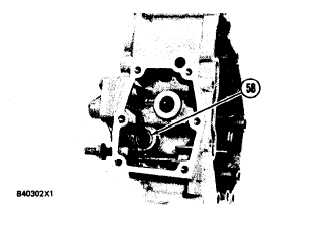
Install check valve (58) in the housing as
shown.
5-116