TM 5-3805-258-24-2
ENGINE
DISASSEMBLY AND ASSEMBLY
12.
13.
14.
ALTERNATOR
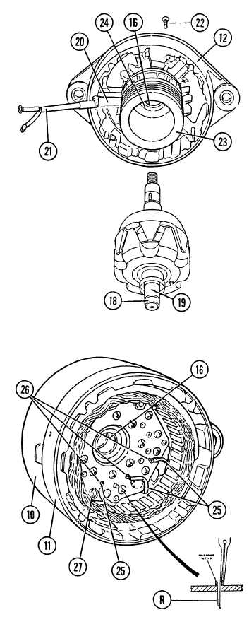
Inspect bearing inner race (18) on rotor
shaft (19) (rectifier end).
Only remove bearing (16) if worn or
damaged. Replace both bearing (16) and
bearing race (18) if bearing is replaced. Use
bearing race puller (tooling C) to remove
bearing race (18).
Remove epoxy from deep groove (20) in
drive end shield.
CAUTION
Epoxy putty covers field winding lead (21) in
next step. Care must be taken when removing this
epoxy so that the lead is not damaged.
15.
16.
17.
18.
19.
20.
Remove six screws (22) on front side of drive
end shield.
Remove pole body (field coil winding) (23)
and lead (21).
Remove intermediate ring (24).
Remove bearing (16) from seat in drive end
shield.
Disconnect three stator phase windings (25)
from the three rectifier bridge terminals (26)
by unsoldering and straightening the bent
over leads.
Remove stator frame (11) from rear housing
(10).
CAUTION
When unsoldering the (R) terminal, do not grip
the soldering sleeve around its outside diameter.
The sleeve will collapse with too much pressure.
While heating with iron, grip the edge with long
nose pliers.
21. Unsolder the soldering sleeve from terminal
“R”.
22. Remove two screws (27).
5-12b


