TM 5-3805-258-24-2
POWER TRAIN
DISASSEMBLY AND ASSEMBLY
DRIVE SHAFT CARRIER BEARING
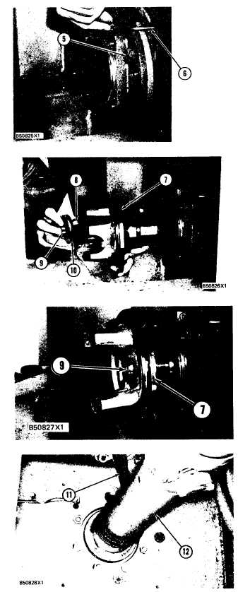
7. Install bolts (5) and the nuts to hold the carrier
bearing and housings in position.
8. Put grease line (6) in position and connect it to
the fittings on each side of the frame.
9. Install yoke (7) for the center drive shaft on the
end of the front drive shaft.
10. Install O-ring seal (8), retainer (10) and bolt
(9) to hold the yoke.
11. Tighten bolt (9) to a torque of 135 ± 15 N-m
(100 ± 11 lb. ft.).
12. Fill the carrier bearing housings with clean
grease and make sure no grease comes out
between the lip type seal and yoke into the
parking brake area. If there is leakage of
grease, a replacement of the lip type seal must
be made in the carrier bearing housing.
13. Remove yoke (7) from the end of the front drive
shaft.
14. Remove strap (11 ) from front drive shaft ( 12).
end by:
a) install parking brake*
*This operation is in the VEHICLE SYSTEMS
DISASSEMBLY AND ASSEMBLY section.
5-194

