TM 5-3805-258-24-2
POWER TRAIN
DISASSEMBLY AND ASSEMBLY
FRONT DRIVE SHAFT AND CENTER DRIVE SHAFT
REMOVE AND INSTALL FRONT
DRIVE SHAFT
3253-C-10
start by:
a) remove drive shaft carrier bearing
CAUTION
Be careful not to damage the carrier bearing
surface on drive shaft (1) when it is lowered on
the frame.
1.
2.
3.
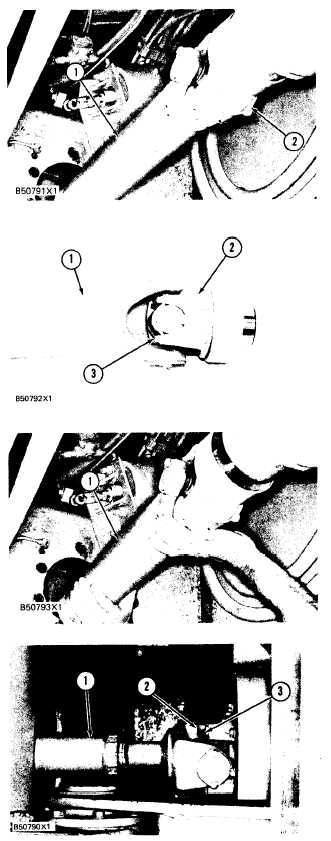
Remove the strap and lower the end of drive
shaft (1) on the frame.
Pull drive shaft (1) and yoke (2) from the dif-
ferential pinion shaft and lower the unit from
the machine.
If necessary. remove bolts (3) and the straps to
remove yoke (2) from the universal joint- and
drive shaft (1).
NOTE: The following steps are for installation.
Make sure all drive shaft yokes are on the same
centerline as shown on the illustration on Page 40.
4. Connect yoke (2) to the universal joint and
drive shaft ( 1 ) with straps and bolts (3).
Tighten bolts (3) to a torque of 55 ± 15 N-m
(41 ± 11 Ib.ft.).
5. Put drive shaft (1) and the yoke in position in
the frame and slide the yoke over the differen-
tial pinion shaft.
end by:
a) install drive shaft carrier bearing
REMOVE INSTALL AND CENTER DRIVE
SHAFT
3253-G-10
1. Make sure the parking brake is released so the
drive shaft can be turned.
2. Remove bolts (3) and straps (2) from both ends
of drive shaft (1) and remove it from the ma-
c h i n e .
NOTE: Make sure all drive shaft yokes are on the
same center line as shown on the illustration on Page
40.
3. Put drive shaft (1) in position and install straps
(2) and bolts (3) as shown. Tighten bolts (3) to
a torque of 55 ± 15 N•m (41 ± 11 lb. ft.).
5-195


