VEHICLE SYSTEMS
TM 5-3805-258-24-2
DISASSEMBLY AND ASSEMBLY
TILT LINK
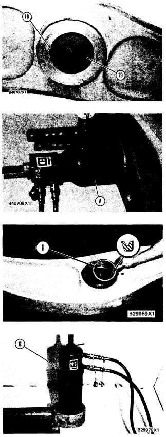
26. Remove lip type seals (18) from each side of the
lever.
27. Remove bearing (19) from the lever.
INSTALL TILT LINK AND LEVER 6116,6117-12
Tools Needed
A
B
C
9S5558 Stud, 1 ¼ in.
1
1
1P544
Nut
1
1
4K684
Washer
1
1
5P3100 Pump Group (or electric)
1
1
6V3175 Hydraulic Puller
1
1
1P1842
Plate
1
9S5431
Sleeve Assembly
1
1P1838
Plate
1
6V4035 Sleeve Assembly
1
1P520
Driver Group
1
1.
2.
3.
4.
Lower the temperature of the bearing and in-
stall it in the lever with tooling (A).
The bearing must be installed in the center of
the bore with the same amount of space on each
side.
Install two lip type seals (1) in the lever. The lip
of the seal must be toward the outside as shown.
Lower the temperature of the bearings and in-
stall them in the center of the bores with the
same amount of space on each side with tooling
(B).
5-315
AND LEVER