TM 5-3805-258-24-2
VEHICLE SYSTEMS
DISASSEMBLY AND ASSEMBLY
REMOVE LOADER FRAME
LOADER FRAME
7054-11
Tools Needed
A
B
C
8S7615 Pin
2
8S8048 Saddle
2
8S7641
Tube
2
8S7630 Stand
2
9S5558 Stud 1 ¼ in.
1
1
1P544
Nut
1
1
4K684
Washer
1
1
6V3175 Hydraulic Puller
1
1
5P3100 Pump Group (or electric)
1
1
6V86
Adapter
1
5H6797 Pin
1
8S6377 Lock
1
9S5433 Adapter
1
9S5431
Sleeve Assembly
1
5P9736 Link Bracket
1
1.
2.
3.
4.
5.
6.
7.
8.
9.
10.
11.
12.
start by:
a) remove bucket
b) remove tilt link and lever
c) remove tilt cylinder
Put caps on the tilt cylinder oil lines.
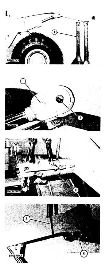
Use the machine hydraulics and lift the loader
frame until the front and rear pin bores are
level.
Install tooling (A) as shown under the loader
frame.
Remove grease fitting (2) from the pin.
Remove bolt (1), the washer and spacer from
the pin.
Fasten a hoist to the lift cylinder.
Install tooling (C) on the pin. Fasten a hoist to
tooling (C) so it does not fall when the pin is
removed.
Remove the pin from the loader frame.
Lower the lift cylinder down on to the main
frame.
Do Steps 3 through 9 for the cylinder on the
other side of the machine.
Retract the cylinders as far as possible.
Fasten straps (3) and a hoist to loader frame
(4) as shown.
5-318