VEHICLE SYSTEMS
TM 5-3805-258-24-2
DISASSEMBLY AND ASSEMBLY
11.
12.
13.
14.
15.
16.
17.
18.
19.
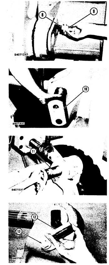
TILT LINK AND LEVER
Install spacer (8), the washer and bolt (9) that
holds the pin in place.
Fasten a hoist to the link and put it in position
on the bucket.
Install pin (10) that connects the link to the
bucket.
Install the spacer, washer and the bolt that
holds the pin in place.
Fasten a hoist to the tilt cylinder and put into
position on the lever assembly.
Install pin (11) that connects the tilt cylinder
and lever assembly.
Install the spacer, washer and bolt (13) that
holds the pin in place.
Install magnet (12) and tighten the two set-
screws that hold the magnet assembly in place.
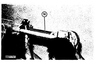
Put the bracket Positioner (14) in position on
the machine and install the bolts that hold it.
5-317