TM 5-3805-258-24-2
VEHICLE SYSTEMS
DISASSEMBLY AND ASSEMBLY
9.
10.
11.
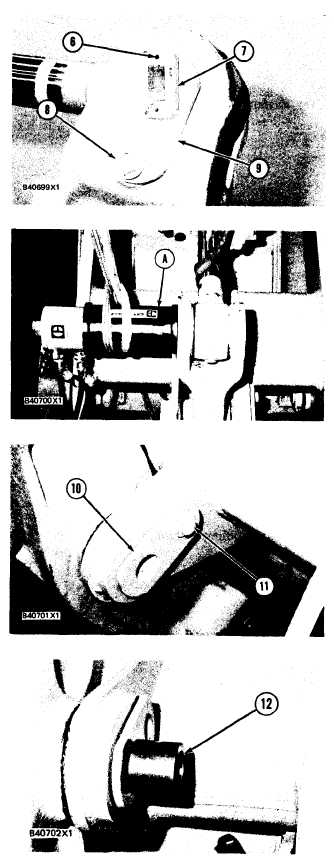
TILT LINK AND LEVER
Loosen setscrews (6) and remove magnet as-
sembly (7) from the pin.
Remove bolt (8), the washer and spacer that
hold pin (9) in place.
Put tooling (A) in position as shown. Fasten a
hoist to tooling (A) and one to the tilt cylinder.
12. Remove the pin with tooling (A).
13.
14.
Move the cylinder rod into the cylinder with the
machine hydraulics and lower the cylinder on
to the loader frame.
Remove bolt (11), the washer and spacer that
holds pin (10) in place.
15. Fasten a hoist to the lever assembly.
16. Put adapter (12) of tooling (B) in the pin.
5-313