TM 5-3805-258-24-2
VEHICLE SYSTEMS
DISASSEMBLY AND ASSEMBLY
TILT LINK AND LEVER
REMOVE TILT LINK AND LEVER 6116 & 6117-11
Tools Needed
A
B
9S5558
Stud, 1 ¼ in.
1
1P544
Nut
1
4K684
Washer
1
5P3100
Pump Group (or electric)
1
1
6V3175
Hydraulic Puller
1
6V4035
Sleeve Assembly
1
9S5556
Adapter
1
6H4158
Pin
2
7S7112
Pin
1
7M9774
Coupling
1
5P7371
Adapter
1
9S8900
Cylinder Group
1
7B2499
Ring
4
5P7370
Sleeve Assembly
1
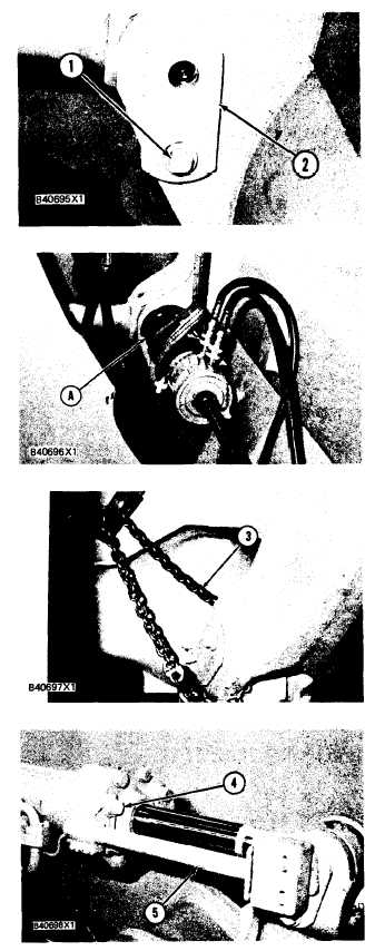
1. Stop the machine with the bucket flat on the
ground.
2. Remove bolt (1) that holds pin (2) to the
bucket.
3. Put tooling (A) in position in the pin.
4. Fasten a hoist to tooling (A) so it will not fall
when the pin is removed.
5. Fasten a hoist to the link assembly so it will not
fall when the pin is removed.
6.
7.
Remove pin (2) from the
Fasten chain (3) to the
hold it in position.
bucket.
tilt lever as shown to
Remove bolts (4) and put bucket positioner (5)
on the loader frame.
5-312

