TM 5-3805-258-24-2
OPERATOR’S STATION
9.
10.
11.
12.
13.
DISASSEMBLY AND ASSEMBLY
ADJUSTABLE STEERING COLUMN
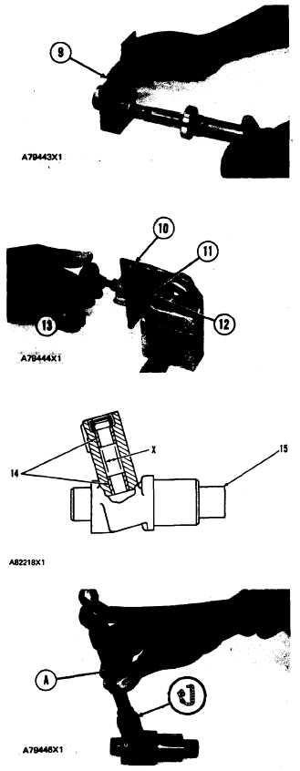
7. Put 1P808 General Purpose Lubricant on the
bearing and in the cap.
8. Install tube assembly and bearing in cap (9).
Install the retainer ring that holds the bearing and
tube assembly in the cap.
Install two bearings (14) in lever (15) with
tooling (A). Install bearings so their outside
edge is even with the counterbores of the lever.
The inside diameter of the bearings after as-
sembly must be 12.667 + 0.051 or — 0.013
mm (.4987 + .0020 or – .0005 in. ) (dimension
x ).
Install the lip seal in the lever with tooling (A).
Put 1P808 General Purpose Lubricant on pin
(12) and install the pin in the cap. Install retainer
ring (11) on the pin.
Install knob (13) and locknut on the pin.
Put 1P808 General Purpose Lubricant in the cap
and install the detent ball and spring. Install set-
screw (10) and tighten until detent ball is tight
against the pin.
5-516

