TM 5-3805-258-24-2
OPERATOR’S STATION
DISASSEMBLY AND ASSEMBLY
ROLLOVER PROTECTIVE STRUCTURE (ROPS)
REMOVE ROLLOVER PROTECTIVE
STRUCTURE (ROPS)
7323-11
Tools Needed
A
6V2157
Link Bracket
3
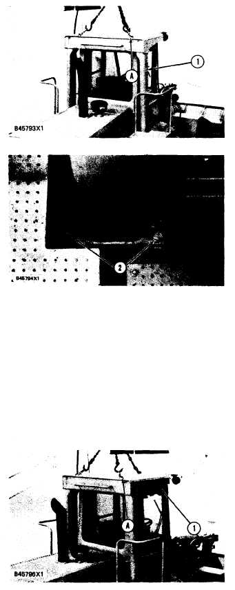
1. Fasten a hoist to the top of ROPS (1) with
tooling (A).
2. Remove bolts (2) and the spacers that hold
each side of the ROPS to the machine.
3. Disconnect wire assemblies near bottom of
right leg of ROPS.
4. Remove ROPS (1) from the machine. The
weight of the ROPS is 563 kg (1250 lb.).
INSTALL ROLLOVER PROTECTIVE
STRUCTURE (ROPS)
7323-12
Tools Needed
A
6V2157
Link Bracket
3
1. Fasten a hoist to the top of ROPS (1) with
tooling (A) and put the unit in position on the
machine.
2. Lower the ROPS and install the spacers and
the bolts to each side. Tighten the bolts to a
torque of 570 ± 80 N•m (420 ± 60 lb.ft.).
3. Connect wire assemblies near bottom of right
leg or ROPS.
5-519