TM 5-3805-258-24-2
OPERATOR’S STATION
DISASSEMBLY AND ASSEMBLY
22.
23.
24.
25.
26.
27.
ADJUSTABLE
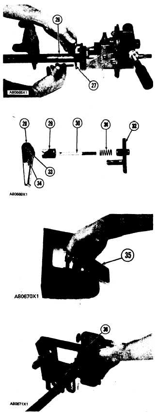
Put column assembly (26) in position on the
housing. Install plate (27) and bolt assembly.
Install bolts that hold the tube assembly to the
housing.
Put shaft (30) in position in lever (28). Install
dowel (33) through the shaft.
Put 1P808 General Purpose Lubricant in the
boss. Put spring (31) in boss (29). Put boss in
position on support (32).
Put lever assembly in position on the support.
Install dowel (34) through the support to hold
lever.
Install steering column tilt lock (35) on bracket
assembly.
Put bracket assembly (36) in position on the
STEERING
steering column support. Install the two nuts on
the shaft of the column tilt lock.
NOTE: When steering column is installed, make an
adjustment to the nuts so the dimension between boss
(29) and support (32) is 13 ± 1 mm (.512 ± .039
in, ).
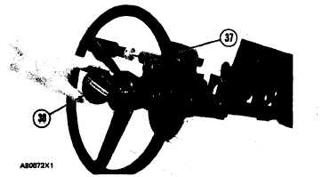
28, Put steering wheel (37) in position on tube
assembly, Install the nut and tighten to a torque
of 50 ± 4 N.m (37 ± 3 lb. ft.).
29. Install cover (38) on the steering wheel.
end by:
a) install adjustable steering column
COLUMN
5-518