TM 5-3805-262-20
INSTALLATION (SHEET 1 OF 3)
(1)
(2)
(3)
(4)
( 5)
(6)
(7)
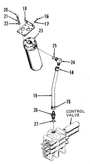
If necessary, position new 0-ring
(27) on connector (26). Install and
tighten 0-ring (27) and connector
(26) in control valve assembly port.
If necessary, position new 0-ring
(25) on elbow (24). Install and
tighten 0-ring (25) and elbow (24)
i n f i l t e r h e a d ( 2 3 ).
Position bracket (18) on filter head
( 2 3 ).
Install and tighten three washers
(22), lock washers (21), and cap-
screws (20).
Connect tube (19) to elbow (24) and
f i n g e r t i g h t e n t u b e f i t t i n g ( 1 4 ).
P o s i t i o n b r a c k e t ( 1 8 ) w i t h f i l t er
head (23) installed and tube (19)
connected in hydraulic reservoir
area. Connect tube (19) to connector
(26) and finger tighten tube fitting
(15). If necessary, use open end
wrench to position elbow (24) to
enable proper positioning of bracket
( 1 8 ).
Install and tighten two lock washers
(17) and capscrews (16).
11-87