TM 5-3805-262-20
7-3. AIR BRAKE SYSTEM MAINTENANCE (CONT)
g. Air Compressor Assembly
(cont).
(3) Air Compressor Governor (cont).
ADJUSTMENT (SHEET 1 OF 2)
Relieve all air pressure before working on air system. Failure to do so
c o u l d r e s u l t i n s e r i o u s i n j u r y . If you are injured obtain medical aid
immediately.
( a)
(b)
(c)
(d)
( e)
( f)
(g)
(h)
( i )
( j )
(k)
Open drain valve in bottom of air
r e s e r v o i r t o r e l i e v e a i r p r e s s u r e.
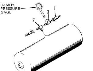
At top of air reservoir, remove
safety valve (1) from tee (2) and
install 1/4 NPTF street tee (3) in
t e e ( 2 ) . I n s t a l l s a f e t y v a l v e ( 1 ) in
s t r e e t t e e ( 3 ) .
Install zero to 150 psi air pressure
g a g e i n s t r e e t t e e ( 3 ).
Close drain valve in bottom of air
r e s e r v o i r .
Start engine and operate at idle speed.
Watch pressure gage. Pressure indication will increase until air com-
pression stops. When pressure indication stops increasing, record
p r e s s u r e i n d i c a t i o n . Pressure indication shall be 105 to 115 psi.
Continue to operate engine at idle speed. Apply brakes several times
while observing pressure gage indication. pressure indication will de-
crease until compression starts. When pressure indication just starts to
i n c r e a s e , r e c o r d p r e s s u r e i n d i c a t i o n. Pressure must be 90-95 psi.
If pressure indications recorded in
steps (f) and (g) above are not cor-
rect perform steps (i) through (1)
below otherwise go to step (m) below.
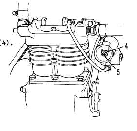
At governor assembly, loosen lock nut
Turn adjusting screw (5) clockwise to
decrease pressure setting, or counter-
clockwise to increase pressure
s e t t i n g.
Tighten lock nut (4) while holding ad-
justing screw (5) using screwdriver to
prevent adjusting screw from moving
and changing adjustment.
7-100