TM 5-3805-262-34
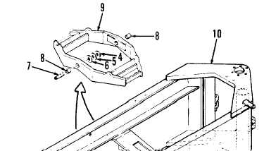
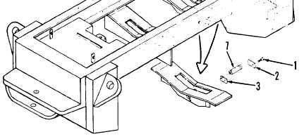
INSTALLATION (SHEET 1 OF 2)
LEGEND
1. Capscrews (4)
2. Lock plates (2)
3. Trunnion retainers (2)
4. Washers (2)
5. Washers (2)
6. Washers (2)
7. Pivot pins (2)
8. Bushings (2)
9. Trunnion assembly
10. Rear chassis
a.
b.
c.
d.
If removed, press two
with outer surface of
rod.
Apply grease to pivot
new bushings (8) into trunnion assembly (9) until flush
trunnion assembly. Use hammer and 2-1/4 inches diameter
pin bores in trunnion assembly (9).
Position trunnion assembly (9) in position
Be sure rear chassis is securely supported
is securely attached to trunnion assembly
ing steps. Failure to do so could cause
beneath loader rear chassis.
and blocked and chain hoist
(9) before performing follow-
serious injury or death by
equipment falling on you. If you are injured by falling equipment;
obtain medical aid immediately.
Connect chain hoist to trunnion assembly (9). Raise trunnion assembly and
aline pivot pin holes in trunnion assembly with pivot pin holes in rear
chassis (10) trunnion supports.
4-261