TM 5-3805-262-34
REASSEMBLY (SHEET 1 OF 3)
NOTE
Lubricate all moving parts using clean calibrating fluid before reassembly.
(1)
(2)
(3)
(4)
(5)
(6)
(7)
(8)
(9)
(10)
(11)
(12)
(13)
(14)
(15)
(16)
Press new plug (72) into one bushing (71).
Install new O-ring (70) on each bushing (71).
Install screw (74) in swivel lever (73).
Guide swivel lever (73) shafts into governor cover (77) bores, with
groove in swivel lever at top of governor cover.
Guide bushings (71) onto swivel lever (73) shafts from outside governor
cover (77). Be sure bushing with plug (72) is on
lever (66) location.
side opposite control
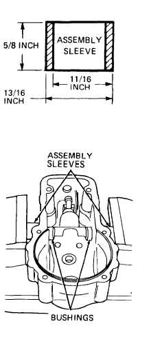
Fabricate two assembly sleeves as shown.
Press bushings (71) into governor cover (77)
bores using vise and two assembly sleeves as
shown. Tighten vise until bushing grooves for
retaining rings (69) are accessible.
Push retaining rings (69) onto bushings (71).
Remove governor cover (77) and assembly sleeves
from vise.
Install new O-ring (68) and original shims (67).
Position control lever (66) on swivel lever (73)
shaft.
Install and tighten lock washer (79) and socket
head capscrew (78). Check swivel lever (73) for
ease of movement by operating control lever (66).
If necessary, disassemble and replace defective
parts to obtain free movement of control and
swivel levers.
Position stop pin (58) in lever link (64), and
drop retainer (63) through lever link bore into
stop pin notch.
Position three springs (60 thru 62) in lever link
bore and secure with retaining clip (59).
Apply grease to stop pin (58).
Put lever link assembly (58 thru 64) in governor cover (77), with flat
side of lever link (64) positioned as noted during disassembly.
3-179