TM 5-3805-262-34
REASSEMBLY (SHEET 2 OF 3)
(17)
(18)
(19)
(20)
(21)
(22)
(23)
(24)
Install bushing
Apply grease to
(65) and new 0-ring (57) .
spring (56) and install spring and spring cap (55).
Insert hooked end of spring (56) projecting from spring cap (55) into
corresponding hole in stop lever (54).
Swing stop lever (54) into position against spring (56) tension and push
onto stop pin (58).
Install and tighten lock washer (53) and capscrew (52). Check stop lever
(54) for ease of movement. If necessary, disassemble and replace defec-
tive parts to obtain free movement of stop lever.
Install full load stop screw (75) and nut (76).
Press bearing plate (44) and spacer (43) into guide sleeve body (42).
Install retaining ring (41).
Install housing (30) and flyweight (23) (see page 3-185).
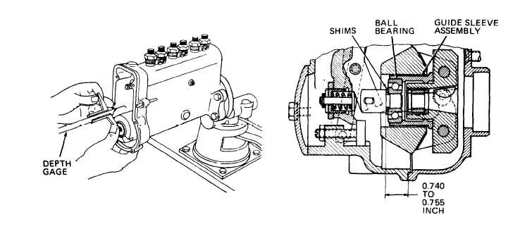
(25) Position guide sleeve assembly (41 thru 44) on flyweight rollers, with
flyweights in rest position. Measure distance between ball bearing inner
race of guide sleeve and gasket surface of housing (30) using depth gage.
(26) Select shims (45) until distance measured in step (25) above plus shim
thickness equals 0.740 to 0.755 inch.
(27) Position selected shims (45) on guide lever (48) knuckle.
3-181


