TM 5-3805-262-34
3-6. WIRING HARNESSES MAINTENANCE (CONT)
a. Front Wiring Harness (Cont).
INSTALLATION (SHEET 3 OF 5)
(24)
(25)
(26)
(27)
(28)
(29)
(30)
(31)
Route front wiring
side driving light
flood light bullet
harness green wire and pink wire over to front right
and flood light. Connect green wire bullet terminal to
terminal. Connect pink wire bullet terminal to driving
light bullet terminal. Do this by alining terminals and firmly pushing
together.
Route front wiring harness green wire and pink wire over to front left
side driving light and flood light. Connect green wire bullet terminal to
flood light bullet terminal. Connect pink wire bullet terminal to driving
light bullet terminal. Do this by alining terminals and firmly pushing
together.
Route front wiring harness orange-green wire and black wire over to
clutch pressure switch installed in side of transmission control valve.
At front wiring harness orange-green wire, separate fuseholder halves by
grasping with fingers, pushing together, twisting counterclockwise, and
pulling apart.
Install 40 ohm resistor in fuseholder half. Assemble fuseholder halves by
grasping both with fingers, alining, then firmly pushing together and
twisting clockwise.
Connect front wiring harness orange-green wire spade terminal and black
wire spade terminal to clutch pressure switch spade terminals. Do this by
grasping terminals in your fingers, alining, and firmly pushing together.
Route front wiring harness white wire over
to neutral start switch installed in trans-
mission control valve. Connect white wire
spade terminal to neutral start switch
spade terminal. Do this by grasping white
wire spade terminal with your fingers,
alining, then firmly pushing onto switch
spade terminal.
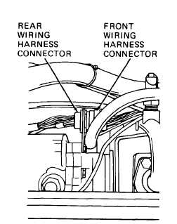
Connect front wiring harness connector to
rear wiring harness connector. Do this by
alining groove in harness connector with
tab in rear wiring harness connector,
pushing firmly, and turning connector nut
clockwise.
3-264