
TM 5-3805-290-23-2
ELECTRICAL GENERAL MAINTENANCE INSTRUCTIONS - CONTINUED
0022 00
ELECTRICAL CONNECTORS INSPECTION - CONTINUED
7.
Inspect connector terminals. Verify terminals are not damaged. Verify terminals are properly aligned and properly
located in connector.
Expected Results. Terminals are properly aligned and terminals appear undamaged.
(1)
If results are OK, proceed to step 8.
(2)
If results are NOT OK, repair or replace connectors. Ensure all seals are properly in place and that connec-
tors are completely connected. Verify repair eliminates the problem.
(3)
If results are NOT OK, replace wiring harness (WP 0169 00 thru WP 0175 00). Ensure all seals are prop-
erly in place and that connectors are completely connected. Verify repair eliminated the problem.
8.
Check individual pin retention in socket.
N OT E
This test is especially important for intermittent faults.
a.
Use new pin. Insert pin into each socket, one at a time, to check for good grip on pin by socket.
b.
Use new socket. Insert socket over each pin, one at a time, to check for good grip on pin by socket. Pins are located
on mating side of connector.
c.
Contact terminal should stay connected when connector is held in position shown in illustration. Contact terminal
is pin or socket.
d.
Expected Results. Pins and sockets appear to be OK.
(1)
If results are OK, end test.
(2)
If results are NOT OK, repair or replace connectors. Ensure all seals are properly in place and that connec-
tors are completely connected. Verify repair eliminates the problem.
(3)
If results are NOT OK, replace wiring harness (WP 0169 00 thru WP 0175 00). Ensure all seals are prop-
erly in place and that connectors are completely connected. Verify repair eliminated the problem.
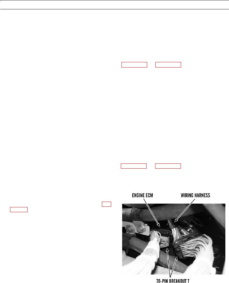
0022 00
INSTALLATION OF BREAKOUT T AND BYPASS HARNESS
70-Pin Breakout T
1.
Disconnect wiring harness from engine ECM (WP
2.
Connect 70-pin breakout T to engine ECM and wiring
harness as shown.
427-B2150
0022 00-20