
TM 5-3805-290-23-2
BRAKE OIL PRESSURE SENSOR REPLACEMENT - CONTINUED
0072 00
C AU T I O N
Wipe area clean around sensor during removal. Plug opening after removing. Contamination of system
could result in premature failure.
N OT E
Use a container to catch any fluid that may drain from hoses or system. Dispose of fluid IAW local policy
and ordinances. Ensure all spills are cleaned up.
REMOVAL
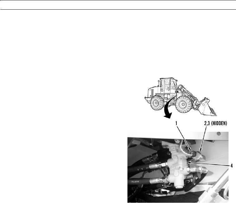
1.
Disconnect wiring harness (1) from brake oil pressure
sensor (2).
2.
Remove brake oil pressure sensor (2) and O-ring (3)
from valve (4). Discard O-ring.
427-B0197
INSTALLATION
1.
Lubricate new O-ring (3) with thin coat of clean oil, install O-ring on brake oil pressure sensor (2), and install assembly
in valve (4). Tighten sensor to 85 18 lb-in. (10 2 Nm).
2.
Connect wiring harness (1) to brake oil pressure sensor (2).
3.
Check oil level and fill hydraulic tank with oil if necessary (TM 5-3805-290-10).
4.
Drive machine (TM 5-3805-290-10).
5.
Verify correct operation of brake system (TM 5-3805-290-10).
6.
Shut down engine (TM 5-3805-290-10).
7.
Check for hydraulic oil leaks.
END OF WORK PACKAGE
0072 00-2