TM 5-3805-290-23-2
RIDE CONTROL ACCUMULATOR MAINTENANCE - CONTINUED
0127 00
TESTING AND CHARGING - CONTINUED
Nitrogen Charging Procedure - Continued
9.
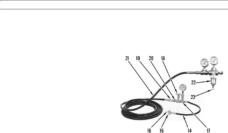
Turn handle (16) on nitrogen charging chuck (15) fully counterclockwise.
10.
Connect nitrogen charging chuck (15) to nitrogen charging valve (12).
11.
Connect hose assembly (14) between nitrogen charg-
ing chuck (15) and T (17).
12.
Install needle valve (18) on one connecting point of T
(17).
13.
Install gage in remaining open port on T (17).
14.
Install coupling assembly (19) in open port of needle
valve (18).
15.
Install nipple (20) on one end of hose assembly (21).
16.
Place open end of hose assembly (21) away from work
area.
427-B1029-1
17.
Open needle valve (18) and turn handle (16) on nitrogen charging chuck (15) fully clockwise.
18.
Raise lift arms fully to momentarily relieve nitrogen pressure charge (TM 5-3805-290-10).
19.
Close needle valve (18).
20.
Lower work tool to ground (TM 5-3805-290-10).
21.
Move lift control lever to FLOAT position (TM 5-3805-290-10).
22.
Connect open end of hose assembly (21) to regulator assembly (22).
23.
Install gage in port directly above regulator.
24.
Install gage in remaining port next to regulator assembly (22).
25.
Install regulator assembly (22) on nitrogen charging valve (12).
26.
Adjust screw (23) on regulator assembly (22) to set pressure on gage to 355 25 psi (2,446 172 kPa).
N OT E
To ensure accumulator nitrogen charge is correct, accumulator piston must be at bottom of accumulator
cylinder. Nitrogen pressure varies with temperature. To obtain most accurate nitrogen charge, temperature
of accumulator should equal outside air temperature. However, temperature of accumulator could be
higher than outside air temperature in some cases. If this is the case, temperature of accumulator should be
used instead of outside air temperature.
27.
Open needle valve (18).
28.
Nitrogen pressure should appear on gage in 10 to 20 seconds.
0127 00-9

