TM 5-3805-291-10
Operation Section
General Information
g01178367
g01178363
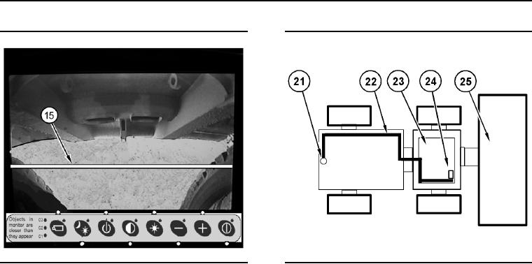
Illustration 3
Illustration 4
Rear Camera View with Marker
Example of a Single Camera Installation on a Wheel Loader
(15) Marker Line
(21)
Rearward Looking Camera
(22)
Possible Video Cable Route
(23)
Machine Cab
Power on/off
(24)
Display in Cab
(25)
Machine Bucket
Power is supplied to the system when the operator turns
Refer to information in the "Display Button Operation"
the key switch to the ON position and the light switch
table or to the "How to Select Display Settings"
selector lever in either STOPLIGHT or SERDRIVE.
section of this document which describes how to
The power On/Off button that is on the display may be
adjust the display settings for a single camera
disabled. Refer to the "Display Description" section of this
system. Make sure the display in not in the "Standby"
document for an Illustration of the power button. The
mode.
power button is shown in the "Display Keypad" Illustration.
Note: If the single camera system can be placed in
Single Camera System Overview
manual mode, PLEASE notify service personnel.
The WAVS single camera system only has one mode
Note: The orientation for the camera image is set
of operation, automatic mode.
during installation. The rearward looking camera
image is set to provide a "reversed" image, similar to
a mirror view. If the camera image orientation is not
correct, contact service personnel immediately.
Multi-Camera System Overview
The WAVS multi-camera system has two modes
of operation, manual mode and automatic mode.
Automatic mode is the preferred mode of operation.
In the automatic mode, the display will provide the
camera view(s) that are defined by the configuration
of the system. The configuration of the system is
determined upon installation of the system.
0004 00-63

