
TM 5-3805-291-23-1
STEERING SYSTEM TESTS, INSPECTIONS, AND ADJUSTMENTS - CONTINUED
0016 00
STEERING NEUTRALIZER VALVE CHECK AND ADJUSTMENT
0016 00
1.
Remove machine to a location that is smooth, level, and hard. The location should be dry and free of debris.
2.
Disconnect steering frame lock (TM 5-3805-291-10).
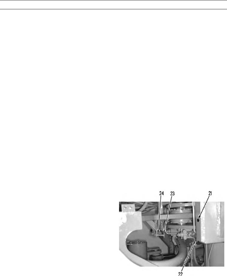
3.
Place ball of putty (21) on left engine end frame (23).
4.
Start and run engine at high idle (TM 5-3805-291-10).
5.
Raise empty bucket to 11.8 in. (30.0 cm).
6.
Disengage parking brake (TM 5-3805-291-10).
7.
Steer machine to left steering stop.
8.
Steer machine straight ahead.
9.
Engage parking brake (TM 5-3805-291-10).
10.
Lower bucket to ground and stop engine (TM 5-3805-291-10).
N OT E
Putty ball should be pressed to 0.50 0.12 in. (12.7 3.0 mm).
11.
Measure thickness of putty ball (21).
N OT E
Turn the striker counterclockwise ifputty is being compressed too much.
Turn the striker clockwise if putty is not being compressed enough.
12.
If necessary, adjust striker (23).
a.
Loosen locknut (24).
b.
Adjust striker (23).
c.
Tighten locknut (24).
13.
If necessary, repeat steps 1 thru 12 until dimension of
putty ball (21) is correct.
14.
Repeat steps 1 thru 13 for opposite side.
427-C0928
0016 00-12