
TM 5-3805-291-23-1
STEERING SYSTEM TESTS, INSPECTIONS, AND ADJUSTMENTS - CONTINUED
0016 00
RELIEF VALVE (STEERING CYLINDER CROSSOVER) TEST AND ADJUSTMENT
0016 00
WAR N I N G
Injury or death to personnel can resultfrom escaping fluid under pressure.
Escaping fluid under pressure, even a small pin-holesize leak, can penetrate body tissue and cause
serious injury and possible death. If fluid is injected into your skin, it must be treated immediately by a
doctor familiar with this type of injury.
CAU T I ON
Care must be taken to ensure that fluids are contained during performance of inspection, maintenance,
testing, adjusting, and repair of the product. Be prepared to collect the fluid with suitable containers before
opening any compartment or disassembling any components containing fluids.
N OT E
Always use a board or cardboard
when checking for a leak.
Dispose of all fluids according to
local regulations and mandates.
1.
Connect steering frame lock (TM 5-3805-291-10).
2.
Relieve hydraulic system pressure (TM 5-3805-291-
10).
427-C1985
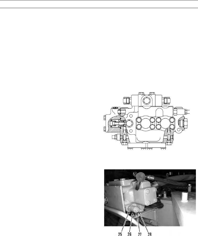
3.
The steering cylinder crossover relief valve is located
in the steering control valve. The steering control
valve is located on the left side of the machine. The
steering cylinder crossover relief valve needs to be
bench tested. Loosen locknut (25) and remove the
valve (26).
4.
The pressure of the relief valve should be 3,713.02
72.52 psi (25,600 500 kPa). Adjust the valve pressure,
if necessary. Loosen the locknut (27). Turn the adjust-
ment screw (28) counterclockwise in order to lower the
pressure of the valve. Turn the adjusting screw clockwise
in order to increase the pressure of the valve. Tighten the
locknut after the correct pressure is reached. The valve is
427-C1986
faulty if the adjustment screw does not affect the pres-
sure. Replace the valve (26) (WP 0127 00).
5.
Install the relief valve into the steering control valve
(26). The valve should be installed with a torque of
44.25 5.16 lb-ft (60 7 Nm).
0016 00-13