
4
TM 5-3805-291-23-2
REAR DRIVE SHAFT REPLACEMENT
THIS WORK PACKAGE COVERS
Removal, Cleaning and Inspection, Installation
INITIAL SETUP
Personnel Required
Maintenance Level
Unit
MOS 62B, Construction Equipment Repairer
Tools and Special Tools
Equipment Conditions
Tool kit, general mechanic's, automotive (Item 90,
Machine parked on level ground (TM 5-3805-291-
10)
Shop equipment, automotive maintenance and
repair: organizational maintenance, common no.
Work tool lowered to ground (TM 5-3805-291-10)
1 (Item 70, WP 0232 00)
Parking brake engaged (TM 5-3805-291-10)
Wrench, torque, click, ratcheting, 1/2" drive, 250
lb-ft (Item 99, WP 0232 00)
Wheels chocked
Materials/Parts
Drawings Required
Cleaning compound, solvent, type III (Item 7, WP
TM 5-3805-291-23P, Figure 94
Grease, molybdenum (Item 17, WP 0233 00)
Estimated Time to Complete Task
Grease, multipurpose (Item 18, WP 0233 00)
3.0 hr
Rag, wiping (Item 35, WP 0233 00)
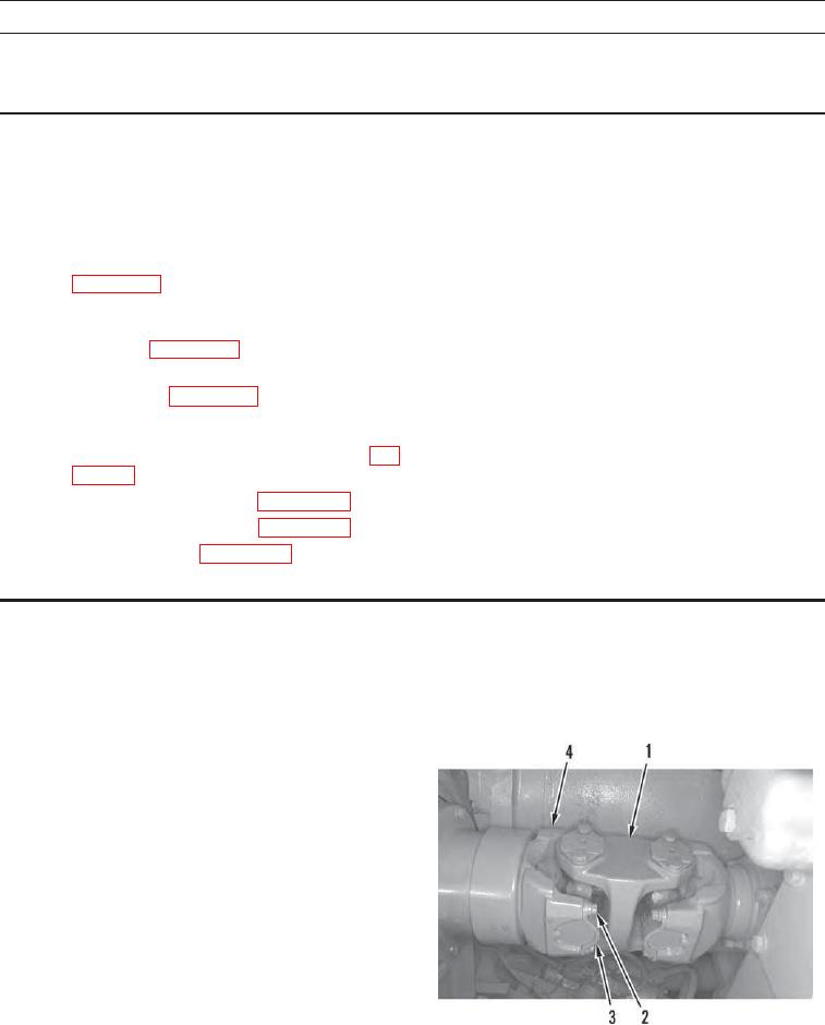
REMOVAL
N OT E
Index mark drive shaft to U-joint to ensure correct installation.
1.
Support rear drive shaft (1) and remove eight bolts (2)
and four straps (3) from each end of rear drive shaft.
2.
Slide yoke (4) rearward to increase clearance and care-
fully remove rear drive shaft (1) from machine.
427-C0453