
TM 5-3805-291-23-2
MAIN CONTROL VALVE AND IMPLEMENT PUMP HYDRAULIC
HOSES, LINES, AND FITTINGS REPLACEMENT - CONTINUED
0157 00
REMOVAL - CONTINUED
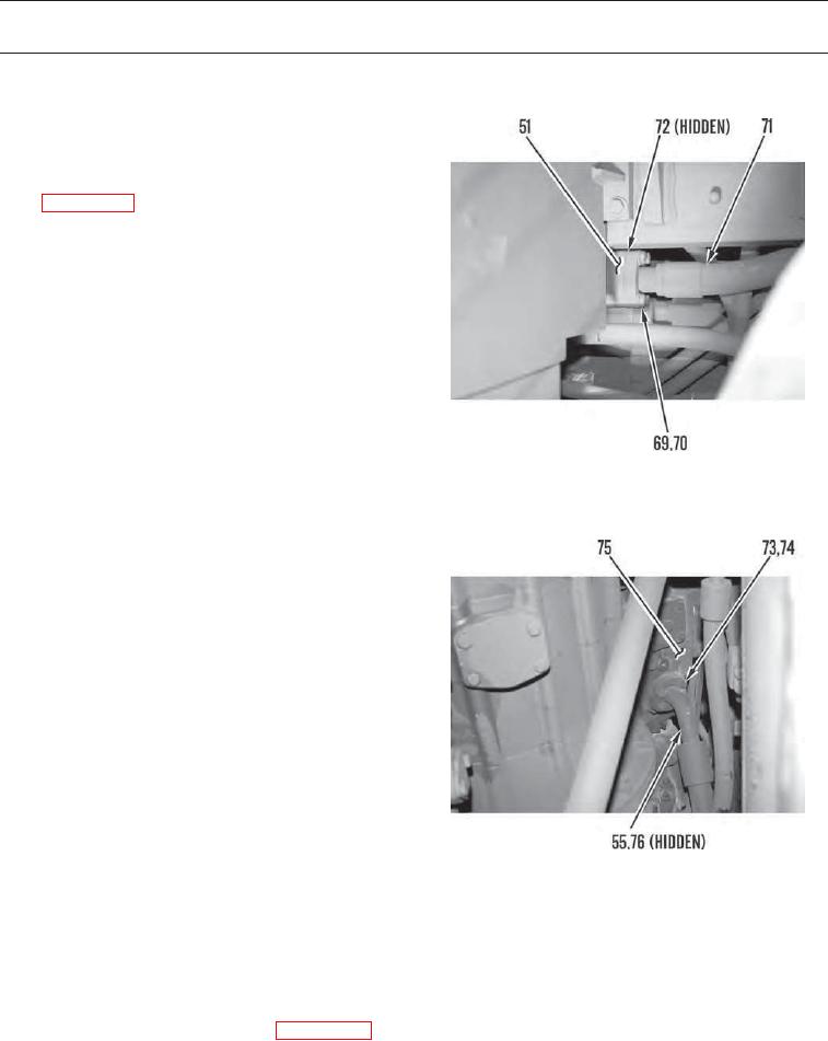
30.
Remove four bolts (69) and washers (70) and
disconnect hose (51) from hose (71). Remove
gasket (72) from hose. Discard gasket.
31.
Disconnect hose (71) from hydraulic tank
(WP 0159 00) and remove hose from machine.
427-C1356
32.
Remove four bolts (73) and washers (74) from
hose (55) and disconnect hose from implement
pump (75). Remove gasket (76) from hose.
Discard gasket.
427-C1357
INSTALLATION
N OT E
Apply a thin coat of clean oil to all O-rings prior to installation.
1.
Install new gasket (76) on hose (55) and position hose on implement pump (75). Install four washers (74) and bolts (73).
2.
Connect hose (71) to hydraulic tank (WP 0159 00).
3.
Install new gasket (72) on hose (71) and connect hose to hose (51). Install four washers (70) and bolts (69).
0157 00-8