
TM 5-3805-291-23-2
FLYWHEEL REPLACEMENT - CONTINUED
0177 00
INSTALLATION
WARN I N G
Use extreme caution when handling heavy parts. Provide adequate support and use assistance during pro-
cedure. Ensure that any lifting equipment used is in good condition and of suitable load capacity. Keep
clear of heavy parts supported only by lifting equipment. Failure to follow this warning may result in injury
or death to personnel.
N OT E
Flywheel weighs approximately 75 lb (34 kg).
1.
With assistance, install flywheel (1) over studs on crankshaft (6).
2.
Install six washers (5) and bolts (4) on flywheel (1). Tighten bolts evenly to 220 30 lb-ft (300 40 Nm).
3.
Install two studs on crankshaft (6) at 9 o'clock and 3 o'clock positions.
4.
Install two washers (3) and bolts (2) on flywheel (1).
Check flywheel runout (refer to Inspection in this work package).
5.
INSPECTION
0177 00
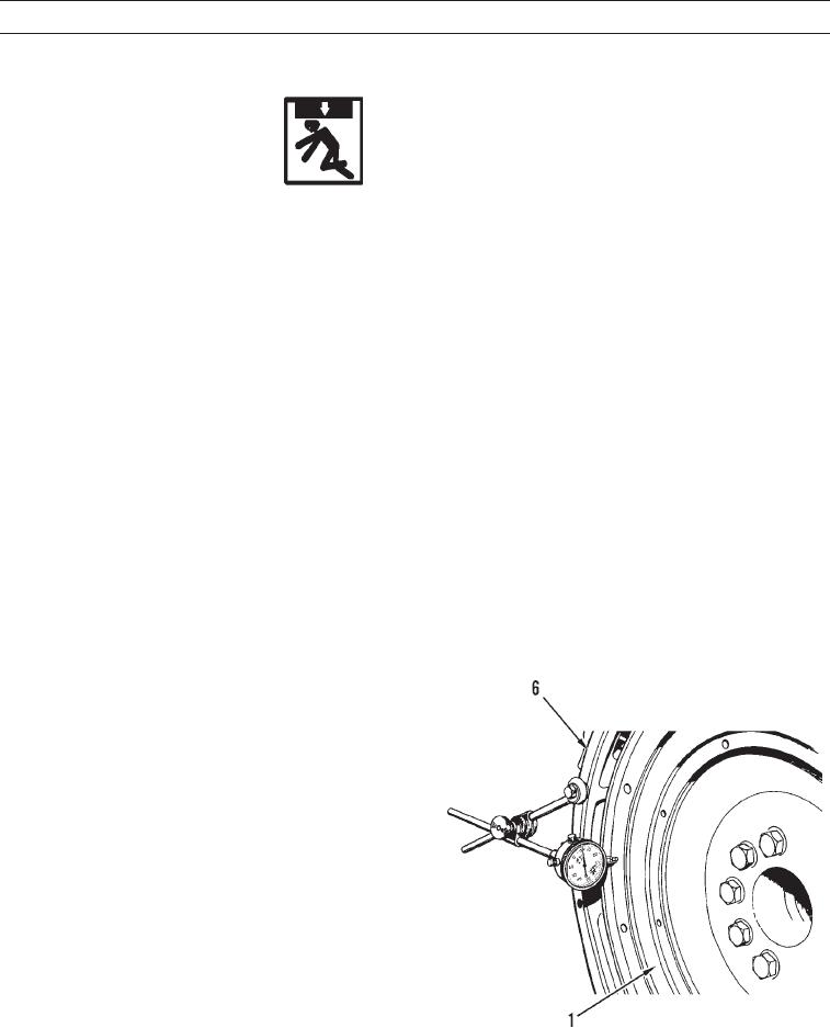
Face Runout (Axial Eccentricity)
N OT E
Find top center position for No. 1 Piston.
Always put force on crankshaft in same direction before dial indicator is read. This will remove any
crankshaft end clearance.
1.
Install dial indicator on bell housing (6) as shown.
2.
Set dial indicator to read 0.00 in. (0.0 mm).
3.
Turn flywheel (1) at intervals of 90 degrees and read
dial indicator.
4.
Take measurements at all four points. Difference
between lower measurements and higher measure-
ments at all four points must not be more than 0.0005
in. (0.013 mm), which is maximum permissible face
runout (axial eccentricity) of flywheel (1).
427-C0556
0177 00-3