
TM 5-3805-291-23-2
FLYWHEEL REPLACEMENT - CONTINUED
0177 00
INSPECTION - CONTINUED
Bore Runout (Radial Eccentricity)
0177 00
N OT E
Find top center position for No. 1 Piston.
Always put force on crankshaft in same direction before dial indicator is read. This will remove any
crankshaft end clearance.
1.
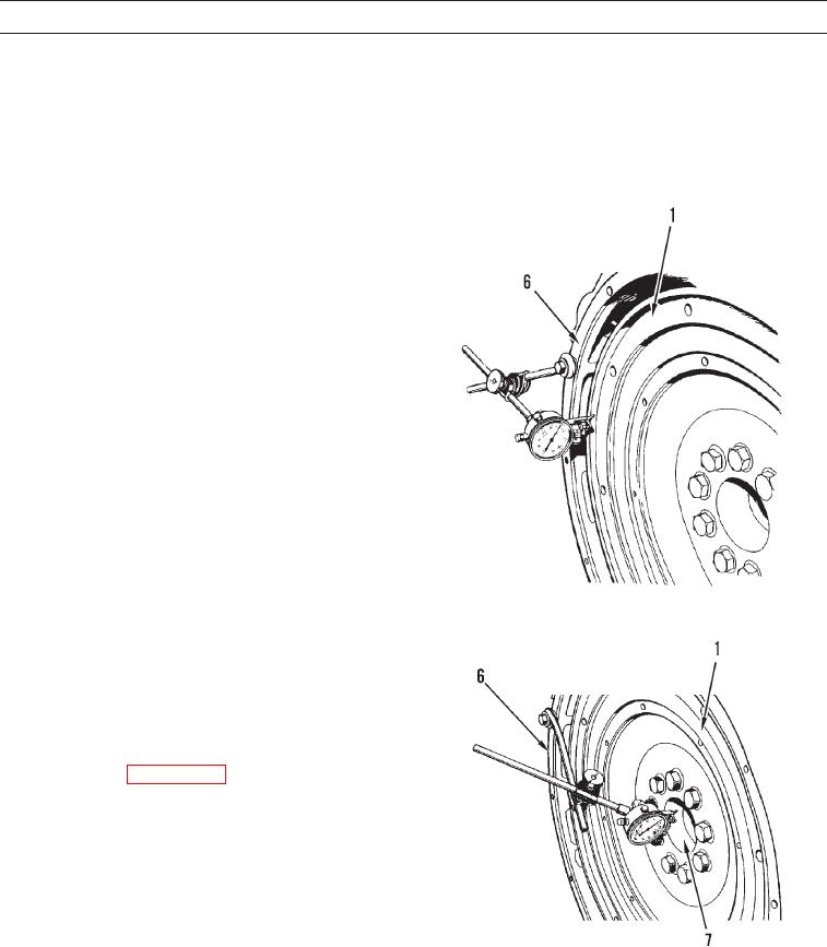
Install dial indicator on bell housing (6) as shown.
2.
Adjust universal attachment so dial indicator makes
contact with flywheel (1).
3.
Set dial indicator to read 0.00 in. (0.0 mm).
4.
Turn flywheel (1) at intervals of 90 degrees and read
dial indicator.
5.
Take measurements at all four points. Difference
between lower measurements and higher measure-
ments at all four points must not be more than 0.006
in. (0.15 mm), which is maximum permissible bore
runout (radial eccentricity) of flywheel (1).
427-C0557
6.
To find runout (eccentricity) of pilot bearing bore (7),
install dial indicator on bell housing (6) as shown and
repeat steps 1 thru 5.
7.
Runout (eccentricity) of pilot bearing bore (7) for pilot
bearing in flywheel (1) must not exceed 0.005 in.
(0.13 mm).
8.
Install engine (WP 0171 00).
427-C0558
9.
Run engine to verify there is no flywheel interference (TM 5-3805-291-10).
10.
Shut down engine and inspect for flywheel interference (TM 5-3805-291-10).
END OF WORK PACKAGE
0177 00-4