
TM 5-3805-292-10
0010
REMOVAL CONTINUED
2. Place hydraulic attachment in neutral position. Stop engine.
WARNING
DO NOT disconnect or remove any hydraulic system line or fitting unless engine is shut
down and hydraulic system pressure has been relieved. Tighten all connections before
applying pressure. Escaping hydraulic fluid under pressure can penetrate the skin,
causing injury or death to personnel.
3. Relieve hydraulic system pressure (WP 0005).
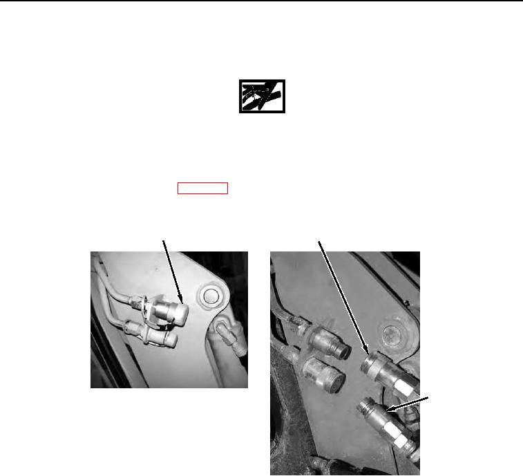
4. With assistance, slide retaining sleeve back and uncouple quick disconnects (Figure 3, Items 2 and 3).
1
2
3
458-0726
Figure 3. Male and Female Disconnects.
0010