
TM 5-3805-292-10
0011
INSTALLATION CONTINUED
0011
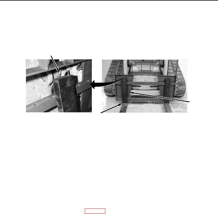
NOTE
Tilt frame back to perform step 6.
6. With assistance, slide tines (Figure 2, Item 3) to desired position on pallet fork frame (Figure 2, Item 2) guide
rails and push down on lock tabs (Figure 2, Item 1) to lock tines in position.
1
2
3
458-0727
Figure 2. Setting Tine Position.
0011
END OF TASK
REMOVAL
0011
WARNING
Before disengaging or engaging attachment coupler to work tool, use extreme caution to
ensure work tool is in a safe and stable position before proceeding. Work tool must not be
loaded. All personnel must stand clear. Failure to follow this warning may result in injury or
death to personnel or damage to equipment.
NOTE
Pallet fork assembly can be removed from machine without removing tines.
1. Lower loader arms against chassis stops and tilt attachment coupler back until work tool is almost on floor but
not touching. Refer to Operating Loader (WP 0005).
WARNING
Do not touch control levers while assistant is locking manual locking levers. Failure to
follow this warning may result in injury or death to personnel.