
TM 5-3805-292-23
0007
HYDRAULIC SYSTEM CONTINUED
Flowmeter Tests - Continued
0007
7. Start engine and run at high idle (TM 5-3805-292-10).
8. Disengage parking brake (TM 5-3805-292-10).
9. Read pressure gauge and record pilot pressure reading at high idle for circuit being tested.
a. Move implement joystick to raise loader control arms (TM 5-3805-292-10) (for Figure 33, Item 1).
b. Move implement joystick to lower loader control arms (TM 5-3805-292-10) (for Figure 33, Item 4).
c.
Move implement joystick to tilt coupler (TM 5-3805-292-10) (for Figure 33, Item 3).
d. Move implement joystick to dump coupler (TM 5-3805-292-10) (for Figure 33, Item 2).
10. Pressure readings should vary from 0 to 360 psi (24.8 bar) at high idle as joystick is moved.
a. If pressure readings are correct, test is complete.
b. If pressure readings are not correct, repair loader control valve (WP 0089).
c.
11. Disconnect extension hose and 600 psi (47.3 bar) gauge from machine.
12. Disconnect jumper wire from seat.
13. Reconnect pilot hoses to valve.
14. Tilt ROPS back.
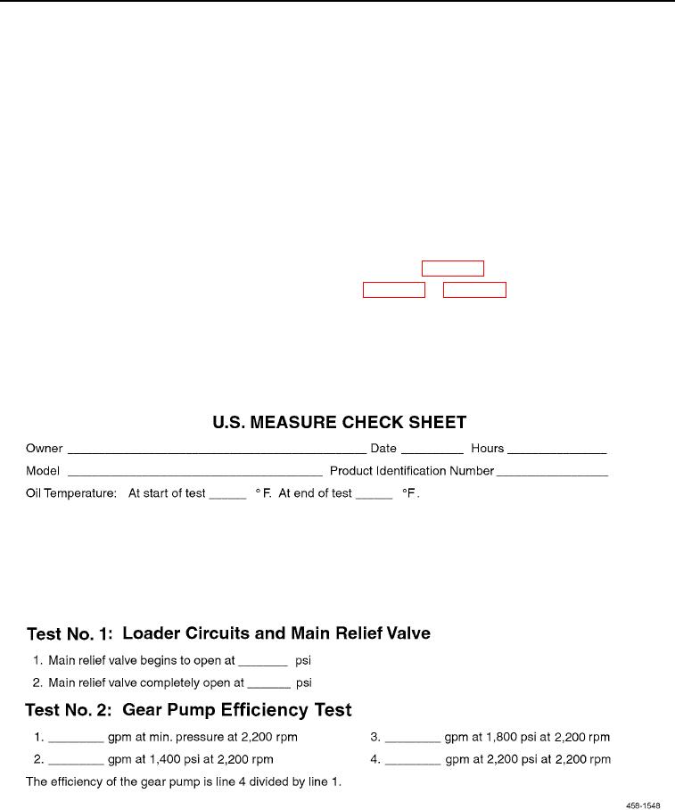
Figure 36. Measure Check Sheet.
0007
END OF TASK
0007-35