
TM 5-3805-292-23
0053
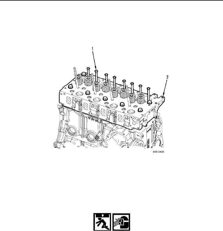
REMOVAL CONTINUED
N OT E
Tag and note location of push rods.
4. Remove eight push rods (Figure 3, Item 1) from cylinder head (Figure 3, Item 2).
Figure 3. Push Rods.
0053
N OT E
Note location of cylinder head bolts to aid in installation.
5. Using inverted torx sockets, remove six bolts (Figure 4, Item 3) and four bolts (Figure 4, Item 2) from cylinder
head assembly (Figure 4, Item 4). Discard bolts.
6. Attach lifting device (Figure 4, Item 1) to cylinder head assembly (Figure 4, Item 4).
WARN I N G
Use extreme caution when handling heavy parts. Provide adequate support and use
assistance during procedure. Ensure that lifting device is in good condition and of suitable
load capacity. Keep clear of heavy parts supported only by lifting device.
Use eye protection when servicing cylinder head.
Failure to follow these warnings may result in injury or death to personnel.
N OT E
Cylinder head weighs 100 lb (45 kg).